×
ToyotaParts- Hello
- Login or Register
- Quick Links
- Live Chat
- Track Order
- Parts Availability
- RMA
- Help Center
- Contact Us
- Shop for
- Toyota Parts
- Scion Parts
My Garage
My Account
Cart
OEM 2010 Scion xD Rack And Pinion
Steering Rack And Pinion- Select Vehicle by Model
- Select Vehicle by VIN
Select Vehicle by Model
orMake
Model
Year
Select Vehicle by VIN
For the most accurate results, select vehicle by your VIN (Vehicle Identification Number).
1 Rack And Pinion found

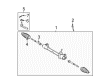
2010 Scion xD Gear Assembly
Part Number: 45510-52211$582.13 MSRP: $853.12You Save: $270.99 (32%)Ships in 1-3 Business DaysProduct Specifications- Other Name: Gear Assembly, Steering; Rack and Pinion Assembly; Steering Gearbox; Steering Gear Assembly
- Replaces: 45510-52210
- Condition: New
- SKU: 45510-52211
- Warranty: This genuine part is guaranteed by Toyota's factory warranty.
2010 Scion xD Rack And Pinion
Looking for affordable OEM 2010 Scion xD Rack And Pinion? Explore our comprehensive catalogue of genuine 2010 Scion xD Rack And Pinion. All our parts are covered by the manufacturer's warranty. Plus, our straightforward return policy and speedy delivery service ensure an unparalleled shopping experience. We look forward to your visit!
2010 Scion xD Rack And Pinion Parts Q&A
- Q: How to remove the power Rack And Pinion on 2010 Scion xD?A: A correct power steering rack and pinion removal starts by aligning the front wheels forward and disconnecting the negative battery cable. Start by removing the front wiper arm head cap and both front wiper arms with their blades from the left side and right side. The next step involves removing the hood to cowl top seal as well as the cowl top ventilator louver sub-assembly and the left cowl top ventilator louver. The procedure demands removal of front wiper motor and link as well as front air shutter seal from the right side and finally outer cowl top panel. To get to the column hole cover silencer sheet installers must remove the floor carpet then two clips. To safeguard the spiral cable users must secure the steering wheel assembly with a seat belt then apply matchmarks to the sliding yoke of the steering intermediate shaft assembly and power steering before loosening bolt A then maintaining bolt B and dissembling the steering intermediate shaft assembly. First separate the body from clip B while taking out clip A to remove the No. 1 steering column hole cover sub-assembly. For the replacement procedures begin by removing the front wheel then carefully separate the tie rod sub-assemblies from left and right sides, then disassemble the front stabilizer assemblies on both sides. The front suspension lower arms need removal from both sides before engine assembly suspension occurs by removing the bolt and wire harness clamp bracket while using Engine Hanger (Part No.: No. 1 engine hanger 12281-37020, No. 2 engine hanger 12282-37010, Bolt 91552-81050) with torque to 43 Nm (439 kgf-cm, 32 ft-lbf). You must use parts Number 1 engine hanger 12281-37020 and Number 2 engine hanger 12282-37010 and Bolt 91552-81050 with 43 Nm (439 kgf-cm, 32 ft-lbf) torque to install them onto the engine support points. Then install an engine sling device with a chain block to hold the engine in position. To remove the front suspension crossmember sub-assembly detach the bolt then divide the engine moving control rod and apply support with a transmission jack while disconnecting the six bolts. Use Special Service Tool 09612-00012 with tape when securing the power steering rack and pinion in a vise before taking out the two bolts and two nuts. Keep these nuts from rotating during bolt turnover procedures. Put matchmarks on the left side of the components before removing both left and right tie rod end sub-assemblies.
Related 2010 Scion xD Parts
 2010 Scion xD Dimmer Switch
 2010 Scion xD Ignition Switch
 2010 Scion xD Rack and Pinion Boot
 2010 Scion xD Steering Angle Sensor
 2010 Scion xD Steering Column
 2010 Scion xD Steering Gear Box
 2010 Scion xD Steering Shaft
 2010 Scion xD Steering Wheel
 2010 Scion xD Tie Rod End
 2010 Scion xD Wiper Switch