×
ToyotaParts- Hello
- Login or Register
- Quick Links
- Live Chat
- Track Order
- Parts Availability
- RMA
- Help Center
- Contact Us
- Shop for
- Toyota Parts
- Scion Parts
My Garage
My Account
Cart
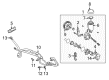
OEM Scion Power Steering Pump
Power Steering Pump Unit- Select Vehicle by Model
- Select Vehicle by VIN
Select Vehicle by Model
orMake
Model
Year
Select Vehicle by VIN
For the most accurate results, select vehicle by your VIN (Vehicle Identification Number).
4 Power Steering Pumps found


Scion Power Steering Pump Part Number: 44310-20870
$361.49 MSRP: $529.76You Save: $168.27 (32%)Ships in 1-3 Business DaysProduct Specifications- Other Name: Pump Assembly, Vane


Scion Power Steering Pump Part Number: 44310-21050
$373.29 MSRP: $547.06You Save: $173.77 (32%)Ships in 1-3 Business DaysProduct Specifications- Other Name: Pump Assembly, Vane; Pump

Scion Power Steering Pump Part Number: 44310-52050
$352.41 MSRP: $516.46You Save: $164.05 (32%)Ships in 1-3 Business DaysProduct Specifications- Other Name: Pump Assembly, Vane

Scion Power Steering Pump Part Number: 44310-52090
$446.84 MSRP: $654.85You Save: $208.01 (32%)Ships in 1-3 Business DaysProduct Specifications- Other Name: Pump Assembly, Vane
Scion Power Steering Pump
OEM parts deliver unmatched quality you can rely on. They pass extensive quality control inspections. Scion produces them to the official factory specifications. This process helps prevent defects and imperfections. So you can get exceptional lifespan and a flawless fit. Need new OEM Scion Power Steering Pump? You'll love our wide selection of genuine options. Shop in minutes and skip the hunt. Our prices are unbeatable, you'll save time and money. It's easy to shop and find the right piece. Our committed customer service team gives professional help from start to finish. Every part includes a manufacturer's warranty. We ship quickly, your parts will arrive fast at your door.
Scion Power Steering Pump converts engine muscle into smooth control of the wheels, thereby enabling the driver to steer with less effort. Scion adopted aggressive marketing such as virtual metropolises and small series of releases, maintained a minimalist pricing structure, and urged color mash-ups that shoppers would stamp their identity on any car as the company compiled actual data on what young drivers purchased and discussed with Toyota. Scion was an experiment on wheels, and it demonstrated that small hatchbacks and coupes could also generate loyalty as long as people owned the design, as opposed to generic showroom offerings. Over a quarter of a million vehicles were sold during the Scion lifetime before the company was discontinued in 2016, but its experiment transformed the way parent companies court first-time buyers and is reflected in the current level of customizable trim running down the line. The Power Steering Pump directs the movement of the crankshaft into hydraulic pressure, which facilitates its racing through the steering rack, multiplying the force of the arms such that in the parking lot, the tires stand still yet the car moves as though the tires are on cold asphalt. The Scion drivers find the Power Steering Pump whispering instead of whining, and that proves it efficient in that it maintains pressure with no leakages or slow reaction at any speed. The Power Steering Pump has durable seals and a balanced rotor in addition to tight clearances to resist fluid cavitation and maintain constant feel. When the fluid volume decreases, the Power Steering Pump makes its complaints by increasing the effort and producing faint groans on the wheel, which also gives a significant warning of the worsening of the safety of steering.
Scion Power Steering Pump Parts and Q&A
- Q: How to service and repair the power steering pump on Scion tC?A:Your first action in servicing or repairing the power steering pump should involve removing the RH front wheel followed by drain pumping the power steering fluid then removing the front fender apron seal RH. Start by extracting the fan and generator V belt before unclipping the No. 1 oil reservoir to pump hose. It is essential to take care when working with the V belt to avoid fluid leakage. The pressure feed tube assembly can be detached through the removal of its bolt and subsequent disconnection from the pump bracket rear while using a 27 mm wrench to maintain pressure port union stability during screw and gasket removal. The vane pump assembly removal begins by disconnecting the oil pressure switch connector followed by using SST 09249-63010 to loosen the 2 bolts which will enable removal of the vane pump. Fix the vane pump assembly inside an SST 09630-00014 (09631-00132) vise prior to removing the rear vane pump bracket and power steering suction union port bolt with O-ring. After removal of the flow control valve and pressure port union and its O-ring the power steering oil pressure switch should be replaced if found damaged. Access the rear vane pump housing by unfastening its 4 bolts and O-ring before you disassemble the shaft sub-assembly with pulley by applying 2 screwdrivers to remove the snap ring. The technician should commence the disassembly by taking out the vane pump rotor and the 10 vane pump plates together with the vane pump cam ring and front vane pump side plate where all components require O-ring removal. The removal of the vane pump housing oil seal requires special care because it may damage the front housing structure. A professional should check the oil clearance between vane pump shaft and bush in housing front by measuring to prevent excess clearance of 0.07 mm (0.0028 inch). The thickness measurement of vane pump plates should fall within the range of 1.405 to 1.411 mm (0.05531 to 0.05555 inch) while maintaining a clearance check between vane pump rotor groove and vane plates under 0.03 mm (0.0012 inch). Check the flow control valve for proper operation and leakage while measuring its compression spring free length to be at minimum 36.9 mm (1.453 inch). The vane pump assembly requires replacement when additional specifications or damage signs appear in any component. To install the new oil seal apply power steering fluid onto its lips before insertion with SST 09950-60010 (09951-00280) or 09950-70010 (09951-07100) while maintaining the precise installation direction. Put the pulley shaft inside slowly while checking for damage to the oil seal lip before placing the front vane pump side plate with O-rings correctly positioned. Enable vane pump cam ring installation by placing its inscribed mark at the top before inserting vane pump rotor and plates where round ends must face outward. Place a new snap ring on the shaft before applying power steering fluid to a fresh O-ring which you will install onto the rear housing after positioning it correctly then applying four bolts with 22 Nm (224 kgf-cm, 16 ft. lbs. of torque. The service bolt installation should proceed after ensuring the pump operates without resistance while measuring the pulley rotating torque where 0.27 Nm (2.8 kgf-cm, 2.4 ft. lbs.) represents an acceptable reading criterion. When mounting the power steering oil pressure switch it should have 21 Nm torque (214 kgf-cm, 15 ft. lbs.) and flow control valve plus compression spring must follow with power steering fluid application before final installation. Mount the pressure port union by applying 69 Nm torque to the new O-ring before securing the rear vane pump bracket at 37 Nm to allow the stopper to contact the body of the pump. The power steering suction port union gets installed using a new O-ring at 12 Nm of torque (122 kgf-cm, 9 ft. lbs.) before the vane pump assembly goes in and the bolts should be tightened at 34 Nm (347 kgf-cm, 25 ft. lbs.) using tool SST 09249-63010. Carefully connect the pressure feed tube assembly and the No. 1 oil reservoir for the pump hose tubing before reinstalling the fan and generator V belt and the front fender apron seal RH along with the front wheel RH. Perform a fluid bleed on power steering then investigate for any fluid leakage.
- Q: How to service and repair the power steering pump on Scion xB?A:The power steering pump servicing process starts with rear wiper removal of both blades from right and left sides along with hood to cowl top seal removal. Cowl top ventilator louvers from both sides need attention while windshield wiper links and cowl panel sub-assemblies must also be detached. You need to drain power steering fluid while you expose and eliminate the vane pump oil reservoir cover. The service flow requires dismounting the front right wheel along with the engine under cover from the right side but before that utilize Special Service Tool: 09023-12701 to separate the pressure feed tube assembly by slowly sliding the clip to disconnect the return hose without fluid leak onto the V belt while also disconnecting the oil pressure sensor connector. Extract the vane pump stay from the rear position by disassembling bolt and stay along with heat insulator before moving to the vane pump assembly where you can remove bolts B and C and adjusting strut yet keep bolt A loose enough for extraction. Use Special Service Tool: 09630-00014 (09631-00132) to fix the vane pump assembly in a vise before taking out the three bolts securing the oil reservoir cap sub-assembly and its oil reservoir along with the O-ring. You need to first disassemble the front pump bracket using two bolts before moving onto the flow control valve with its O-ring as well as the power steering oil pressure sensor from the front housing. Rotate the shaft sub-assembly with pulley out by using two screwdrivers to remove the snap ring. Then separate the shaft from the assembly using two screwdrivers. After that, detach the rear vane pump housing through removal of four bolts and its O-ring. The vane pump rotor plates and front vane pump side plate together with its O-rings must be removed. A screwdriver along with cloth allows you to remove the housing oil seal from its position without damaging the front housing area. The front vane pump shaft and its bush in the housing should be investigated for oil clearance which must stay below 0.07 mm (0.0028 inch) and the vane pump rotor and plates must have a thickness between 1.405 to 1.411 mm (0.05531 to 0.05555 inch). Check the flow control valve for proper functioning while inspecting for leaks and measure the compression spring length must exceed 29.2 mm (1.150 inch). The vane pump assembly needs replacement when the pressure port union develops damage. Reassembly requires a freshly coated power steering fluid applied on the new housing oil seal by using Service Tools 09950-60010 (09951-00280) along with 09950-70010 (09951-07100) and a press before inserting the shaft sub-assembly with pulley while avoiding oil seal lip damage. Insert new O-rings to the vane pump side plate before placing the cam ring and rotor and plates inside the pump while verifying appropriate installation orientation. First install a new snap ring to the shaft before applying power steering fluid to an O-ring which then gets installed on the rear housing by aligning the cam ring and front housing and using four bolts with torque set to 22 Nm (224 kgf-cm, 16 ft. lbs.). Follow these steps in order to install the power steering system components: first check the pump for smooth rotation then install the pressure sensor with an O-ring at 21 Nm (214 kgf-cm, 15 ft. lbs.) then the flow control valve and its components at 69 Nm (704 kgf-cm, 51 ft. lbs.). The assembly process requires the vane pump oil reservoir components with a new O-ring to be installed at 9.0 Nm (92 kgf-cm, 80 inch lbs.) followed by attaching the front pump bracket and installing the oil reservoir cap sub-assembly. For installation, coat indicated parts with power steering fluid, temporarily install the vane pump assembly with bolt A, then secure the adjusting strut with bolt B at 44 Nm (449 kgf-cm, 32 ft. lbs.) and bolt C. Install the rear vane pump stay and heat insulator, ensuring proper torque, then connect the pressure feed tube assembly using Special Service Tool: 09023-12701 at 41 Nm (414 kgf-cm, 30 ft. lbs.), ensuring proper installation and reconnect the return hose and oil pressure sensor connector. Adjust the vane pump V belt while checking drive belt deflection and tension and add power steering fluid and bleed air from the system before reinstallation of the engine under cover and front wheel with 103 Nm (1,050 kgf-cm, 76 ft. lbs.) torque. Conclude the procedure by inspecting power steering fluid level in the reservoir before reinstalling vane pump oil reservoir cover and cowl panel sub-assembly together with windshield wiper link assembly and cowl top ventilator louvers and hood to cowl top seal and both front wiper arm and blade assemblies.