×
ToyotaParts- Hello
- Login or Register
- Quick Links
- Live Chat
- Track Order
- Parts Availability
- RMA
- Help Center
- Contact Us
- Shop for
- Toyota Parts
- Scion Parts
My Garage
My Account
Cart
OEM Scion Camshaft
Cam- Select Vehicle by Model
- Select Vehicle by VIN
Select Vehicle by Model
orMake
Model
Year
Select Vehicle by VIN
For the most accurate results, select vehicle by your VIN (Vehicle Identification Number).
24 Camshafts found


Scion Camshaft Part Number: 13501-21030
$257.34 MSRP: $367.42You Save: $110.08 (30%)Ships in 1-3 Business DaysProduct Specifications- Other Name: Camshaft Sub-Assembly


Scion Camshaft Part Number: 13501-47020
$267.71 MSRP: $382.22You Save: $114.51 (30%)Ships in 1-3 Business DaysProduct Specifications- Other Name: Camshaft Sub-Assembly
- Replaces: 13501-0Y100


Scion Camshaft Part Number: 13501-28060
$343.78 MSRP: $503.81You Save: $160.03 (32%)Product Specifications- Other Name: Camshaft Sub-Assembly
- Replaces: 13501-0H040, 13501-0H050

Scion Camshaft, Driver Side Part Number: SU003-06240
$239.41 MSRP: $317.89You Save: $78.48 (25%)Ships in 1-3 Business DaysProduct Specifications- Other Name: Camshaft Cp-Exhaust Left-Hand
- Position: Driver Side
- Replaces: SU003-00183

Scion Camshaft, Driver Side Part Number: SU003-06238
$239.41 MSRP: $317.89You Save: $78.48 (25%)Ships in 1-3 Business DaysProduct Specifications- Other Name: Camshaft Cp-Intake Left-Hand
- Position: Driver Side
- Replaces: SU003-00182

Scion Camshaft, Passenger Side Part Number: SU003-06236
$239.41 MSRP: $317.89You Save: $78.48 (25%)Ships in 1-3 Business DaysProduct Specifications- Other Name: Camshaft Cp-Exhaust Right-Hand
- Position: Passenger Side
- Replaces: SU003-00181

Scion Camshaft, Passenger Side Part Number: SU003-06234
$239.41 MSRP: $317.89You Save: $78.48 (25%)Ships in 1-3 Business DaysProduct Specifications- Other Name: Camshaft Cp-Intake Right-Hand
- Position: Passenger Side
- Replaces: SU003-00180

Scion Camshaft Part Number: 13502-28010
$356.95 MSRP: $523.11You Save: $166.16 (32%)Ships in 1-3 Business DaysProduct Specifications- Other Name: Camshaft Sub-Assembly
- Replaces: 13502-0H010, 13502-0H020

Scion Camshaft Part Number: 13502-36030
$372.95 MSRP: $546.56You Save: $173.61 (32%)Ships in 1-3 Business DaysProduct Specifications- Other Name: Camshaft Sub-Assembly
- Replaces: 13502-0V010, 13502-36010

Scion Camshaft Part Number: 13501-36050
$383.28 MSRP: $561.70You Save: $178.42 (32%)Ships in 1-3 Business DaysProduct Specifications- Other Name: Camshaft Sub-Assembly
- Replaces: 13501-0V010, 13501-36020

Scion Intake Camshaft Part Number: 13501-WB001
$139.28 MSRP: $197.17You Save: $57.89 (30%)Product Specifications- Other Name: Camshaft Sub-Assembly; Camshaft

Scion Exhaust Camshaft Part Number: 13502-WB001
$139.95 MSRP: $198.13You Save: $58.18 (30%)Ships in 1-3 Business DaysProduct Specifications- Other Name: Camshaft Sub-Assembly; Camshaft

Scion Camshaft Part Number: 13501-0T030
$255.86 MSRP: $365.30You Save: $109.44 (30%)Ships in 1-3 Business DaysProduct Specifications- Other Name: Camshaft Sub-Assembly


Scion Camshaft Part Number: 13502-21031
$266.19 MSRP: $380.06You Save: $113.87 (30%)Ships in 1-3 Business DaysProduct Specifications- Other Name: Camshaft Sub-Assembly

Scion Camshaft Part Number: 13502-47010
$270.06 MSRP: $385.59You Save: $115.53 (30%)Ships in 1-3 Business DaysProduct Specifications- Other Name: Camshaft Sub-Assembly
- Replaces: 13502-0Y080

Scion Intake Camshaft Part Number: 13501-37040
$277.37 MSRP: $396.03You Save: $118.66 (30%)Ships in 1-2 Business DaysProduct Specifications- Other Name: Camshaft Sub-Assembly; Camshaft
Scion Exhaust Camshaft Part Number: 13502-37050
$293.45 MSRP: $418.98You Save: $125.53 (30%)Ships in 1-2 Business DaysProduct Specifications- Other Name: Camshaft Sub-Assembly; Camshaft

Scion Camshaft Part Number: 13502-28030
$323.51 MSRP: $461.90You Save: $138.39 (30%)Ships in 1-3 Business DaysProduct Specifications- Other Name: Camshaft Sub-Assembly
- Replaces: 13502-0H030, 13502-0H040
Scion Camshaft, Driver Side Part Number: SU003-06241
$239.41 MSRP: $317.89You Save: $78.48 (25%)Ships in 1-3 Business DaysProduct Specifications- Other Name: Camshaft Cp-Exhaust Left-Hand; Camshaft, Exhaust, Driver Side
- Position: Driver Side
- Replaces: SU003-04744

Scion Camshaft Part Number: 13501-28040
$359.22 MSRP: $526.44You Save: $167.22 (32%)Product Specifications- Other Name: Camshaft Sub-Assembly
- Replaces: 13501-0H020
| Page 1 of 2 |Next >
1-20 of 24 Results
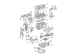
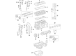
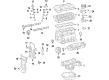
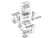
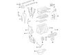
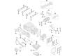
Scion Camshaft
OEM parts deliver unmatched quality you can rely on. They pass extensive quality control inspections. Scion produces them to the official factory specifications. This process helps prevent defects and imperfections. So you can get exceptional lifespan and a flawless fit. Need new OEM Scion Camshaft? You'll love our wide selection of genuine options. Shop in minutes and skip the hunt. Our prices are unbeatable, you'll save time and money. It's easy to shop and find the right piece. Our committed customer service team gives professional help from start to finish. Every part includes a manufacturer's warranty. We ship quickly, your parts will arrive fast at your door.
Scion Camshaft times engine breathing with tough precision and unlocking smooth power on a regular basis. Born in 2003, Scion pursued young customers with no-nonsense pricing, provocative paint and a purchasing experience that had thrown away haggling and hidden prices. It made showrooms playgrounds, held virtual races, and released limited Release Series runs, which went away overnight among collectors. It was the experimental division of Toyota to test aberrant dashboards, booming stereos, and snapping body kits which were later introduced to the mainstream. Over a million first-time owners put it into compact rides that were personal the first day and small did not mean small. The attitude persists in badge mates even after 2016 that continue to value individuality over conformity and afford fun inexpensively. Scion demonstrated how small cars could walk tall without their inflated price tags or corporate bling. Within any contemporary Scion engine, the Camshaft is rotated in unison with the crankshaft because the intake and exhaust valves are opened at precisely the opportune time letting the fuel burn clean and delivering torque to the engine at the first opportunity. The Camshaft is made of hardened steel and is able to withstand high revs and heat, maintaining a steady valve lift through every mile to ensure rock-solid reliability. Single-overhead or dual-overhead design allows the Camshaft to fit breathing in the city thrift or the highway pull without swaps or adjustments. Combined with intelligent injection maps, the Camshaft helps any Scion be economical during driving time at traffic but aggressive when the green light goes on.
Scion Camshaft Parts and Q&A
- Q: How to install the camshaft on Scion xB?A:The installation of the camshaft begins with aligning the timing gear and camshaft while the straight pin remains separate from the key groove followed by slow gear rotation while applying gentle pressure until the pin slots into position. Avoid rotating the gear toward the retard angle direction. Tighten the flange bolt to 551 kgf-cm (54 Nm, 40 ft-lbf) after ensuring the camshaft and gear fringe have no spacing. Check if the camshaft timing gear can reach the retard angle side while being securely locked into the most retarded position. You must apply a light distribution of engine oil to the camshaft journal before you install the timing chain onto the camshaft timing gear with the paint marks facing the timing marks. After that you should check the front numbers and marks before inserting the bearing caps into the cylinder head. After applying oil to bearing cap bolts and their threads and bolt heads uniformly tighten the 10 bearing cap bolts by first following the specific sequence to reach 9.0 Nm for the No. 3 bearing and 30 Nm for the No. 1 bearing. The oiling procedure should begin with the journal portion before aligning the chain paint mark to the camshaft sprocket timing mark followed by set bolt tightening for the camshaft timing sprocket and marks and number verification before bearing cap installation. Saturate the bearing cap bolt threads and their heads using engine oil followed by equal and uniform tightening of the 10 bearing cap bolts with No. 2 bearing at 30 Nm (301 kgf-cm, 22 ft-lbf) and No. 3 bearing at 9.0 Nm (92 kgf-cm, 80 in-lbf). Then hold the camshaft with a wrench while tightening the camshaft timing sprocket set bolt to 54 Nm (551 kgf-cm, 40 ft-lbf) without damaging the valve lifter. The paint marks on both the chain and the camshaft timing gear and camshaft timing sprocket must align with their respective timing marks. Additionally, the crankshaft pulley groove must be directly in line with the timing mark zero located on the timing mark chain cover. The installation of the No. 1 chain tensioner assembly requires releasing the ratchet pawl while pushing in the plunger and hooking it to the pin followed by installing new gaskets and fastening two nuts until torque reaches 9.0 Nm (92 kgf-cm, 80 in-lbf). During post-installation the crankshaft should be turned counter-clockwise to remove the plunger knock pin from its hook position before turning it clockwise to verify the plunger extension position. Install the cylinder head cover sub-assembly by removing old packing material then applying Toyota Genuine Seal Packing Black or Three Bond 1207B or equivalent to specified locations before installing the oil pan within 3 minutes and avoiding engine oil additions for at least 2 hours post-installation. Install the cylinder head cover using 8 bolts and 2 nuts, apply torque of 11 Nm (112 kgf-cm, 8 ft-lbf) to Bolt A while Bolts B requires 14 Nm (143 kgf-cm, 10 ft-lbf) and the nut requires the same torque of 11 Nm (112 kgf-cm, 8 ft-lbf). The engine wires should be installed with 2 bolts at 8.4 Nm (86 kgf-cm, 74 in-lbf) and 2 ventilation hoses must be attached to the cylinder head cover. When completing the installation sequence you should perform a spark plug and ignition coil assembly assembly before checking for oil leaks then verifying ignition timing and finally taking out the No. 1 engine cover sub-assembly and installing the rear engine under cover RH.
- Q: How to replace the camshaft on Scion xA?A:The first step is to remove cylinder head cover No.2 by unfastening its 4 nuts. Unscrewing the 4 bolts from ignition coil No.1 allows its extraction along with the 4 ignition coils. Both ventilation hoses must be detached from the cylinder head cover before removing the total sub-assembly which requires 9 bolts and 2 nuts. Initiate the camshaft replacement after removing the engine under cover RH to proceed with removing No.2 camshaft where proper crankshaft damper rotation must start at a 40 degrees angle below TDC to stop piston-valve interaction. Align the timing marks on No.1 cylinder while placing it at TDC/compression position and mark the timing chain. Begin by removing the screw plug with an 8 mm hexagon wrench then position the screwdriver within the chain tensioner service hole to hold the stopper plate in an upward direction. By turning the camshaft No.2 clockwise the chain tensioner plunger pushes in and a 2 to 3 mm diameter bar needs to be used to keep the stopper plate secure. Use Special Service Tool: 09023-38400 as a wrench to remove the bolt located on the hexagonal lobe while following the instructions. Loosen and remove the 11 bearing cap bolts along with the 5 bearing caps evenly. Taxi the No.2 camshaft into the air before removing it together with its camshaft timing sprocket. When removing the camshaft and camshaft timing gear assembly with its timing chain, tie the chain to a string to prevent items from falling into the timing chain cover while performing the following steps: First loosen the 8 bearing cap bolts and 4 bearing caps uniformly. Then remove the bearing caps after holding the timing chain. You should clamp the camshaft in a vise while applying tape on the 4 oil paths of the cam journal and using punctuations on the tape to mark the advance and retard oil paths. The correct operation with compressed air pressure allows users to check that the camshaft timing gear assembly performs rotational movements during the timing advance phase. Mindfully unscrew the fringe bolt from the camshaft timing gear assembly but maintain the presence of all other 4 bolts and release the lock pin in case of reusable camshaft timing gear use. The camshaft timing gear assembly and camshaft should be installed while rotating the gear clockwise and forcing it toward the camshaft until no gaps exist between the gear fringe and camshaft. Secure the fringe bolt to 64 Nm (653 kgf-cm, 47 ft. lbs.) torque value while verifying that the camshaft timing gear assembly achieves the retard angle with locking at its most advanced position. Start with engine oil on the camshaft journals before placing the timing chain properly on the camshaft timing gear by aligning the paint mark then fully tighten the specified bolt sequence to 13 Nm (129 kgf-cm, 9.4 ft. lbs.) with uniformity maintained. The No.2 camshaft installation requires a timing chain holder to position the paint mark with the timing mark before installing the sprocket and tightening the bolts to equal torque values. You need to apply torque on bearing cap No.1 at 23 Nm (235 kgf-cm, 17 ft. lbs.) while holding the camshaft with a wrench and using Special Service Tool: 09023-38400 to install the bolt to 64 Nm (653 kgf-cm, 47 ft. lbs.). Check the alignment of all timing marks after aligning the crankshaft damper timing notch to timing mark "0" while removing the bar from the timing chain tensioner. Seal packing (Part No. 08833-00070 or equivalent) needs application onto the screw plug end before installing it with 15 Nm (153 kgf-cm, 11 ft. lbs.) torque. The installation requires the cylinder head cover sub-assembly with seal packing (part number 08826-00080 or equivalent) and should be installed within 3 minutes after thoroughly cleaning all contact surfaces of oil. Apply a torque force of 10 Nm (102 kgf-cm, 7.4 ft. lbs.) to fasten the 9 bolts along with 2 seal washers and 2 nuts onto the cylinder head cover. The last procedure includes installing ignition coil No.1 with 9.0 Nm (92 kgf-cm, 80 inch lbs.) torque while tightening nut A, followed by bolt B with 7.0 Nm (71 kgf-cm, 62 inch lbs.) torque until all engine oil leaks are checked.