×
ToyotaParts- Hello
- Login or Register
- Quick Links
- Live Chat
- Track Order
- Parts Availability
- RMA
- Help Center
- Contact Us
- Shop for
- Toyota Parts
- Scion Parts
My Garage
My Account
Cart
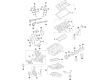
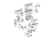
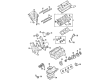
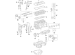
OEM Toyota Highlander Cylinder Head Gasket
Engine Cylinder Head Gasket- Select Vehicle by Model
- Select Vehicle by VIN
Select Vehicle by Model
orMake
Model
Year
Select Vehicle by VIN
For the most accurate results, select vehicle by your VIN (Vehicle Identification Number).
14 Cylinder Head Gaskets found


Toyota Highlander Head Gasket Part Number: 11115-0P030
$54.48 MSRP: $75.83You Save: $21.35 (29%)Ships in 1-2 Business Days


Toyota Highlander Head Gasket Part Number: 11115-28040
$74.52 MSRP: $104.61You Save: $30.09 (29%)Ships in 1-3 Business Days

Toyota Highlander Gasket, Cylinder Head Part Number: 11116-31060
$69.43 MSRP: $97.46You Save: $28.03 (29%)Ships in 1-3 Business Days

Toyota Highlander Head Gasket Part Number: 11116-0P020
$70.02 MSRP: $98.29You Save: $28.27 (29%)Ships in 1-3 Business Days


Toyota Highlander Head Gasket Part Number: 11115-0P020
$72.04 MSRP: $101.12You Save: $29.08 (29%)Ships in 1-3 Business Days


Toyota Highlander Head Gasket Part Number: 11116-20051
$72.63 MSRP: $101.94You Save: $29.31 (29%)Ships in 1-3 Business Days


Toyota Highlander Head Gasket Part Number: 11115-0V011
$83.53 MSRP: $117.25You Save: $33.72 (29%)Ships in 1-2 Business Days

Toyota Highlander Head Gasket Part Number: 11115-31080
$85.78 MSRP: $120.42You Save: $34.64 (29%)Ships in 1-3 Business Days
Toyota Highlander Head Gasket Part Number: 11116-0P030
$55.56 MSRP: $77.32You Save: $21.76 (29%)Ships in 1-3 Business Days
Toyota Highlander Head Gasket Part Number: 11116-20032
$65.52 MSRP: $91.97You Save: $26.45 (29%)Ships in 1-3 Business DaysToyota Highlander Gasket, Cylinder Head Part Number: 11115-20032
$67.53 MSRP: $94.80You Save: $27.27 (29%)Ships in 1-3 Business Days

Toyota Highlander Head Gasket Part Number: 11115-F0030
$72.63 MSRP: $101.94You Save: $29.31 (29%)Ships in 1-2 Business Days
Toyota Highlander Head Gasket Part Number: 11115-20051
$79.03 MSRP: $110.93You Save: $31.90 (29%)Ships in 1-3 Business Days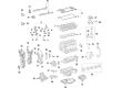
Toyota Highlander Head Gasket Part Number: 11115-F0010
$95.03 MSRP: $133.38You Save: $38.35 (29%)Ships in 1-3 Business Days
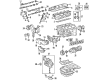
Toyota Highlander Cylinder Head Gasket
Choose genuine Cylinder Head Gasket that pass strict quality control tests. You can trust the top quality and lasting durability. Shopping for OEM Cylinder Head Gasket for your Toyota Highlander? Our website is your one-stop destination. We stock an extensive selection of genuine Toyota Highlander parts. The price is affordable so you can save more. It only takes minutes to browse and find the exact fit. Easily add to cart and check out fast. Our hassle-free return policy will keep you stress-free. We process orders quickly for swift delivery. Your parts will arrive faster, so you can get back on the road sooner.
The Cylinder Head Gasket is a part and parcel of the automotive system which is famous for its durability and output in general for different models of Highlander's. This applies the final coat in the engine block and cylinder head closing it in a manner that it cannot release combustion gases or allow oil and coolant intermingling which is vital in the safety of the engine and its efficiency. A common feature of the Toyota Highlander is the Multi-Layer Steel (MLS) Cylinder Head Gasket commonly associated with good performance and durability to increase engine efficiency and performance. If the Cylinder Head Gasket is to fail, the Highlander's maintenance becomes important since engine knocking and leaks are bound to occur, given their severity. This component is suitable for both five and seven passenger Highlander models, for front wheel or all wheel drive, making it even more useful. The Cylinder Head Gasket not only plays a major role in boosting the performance rate of an engine but also a critical part in the fuel efficiency that is so much valued in the automotive industry. Given its complex and sturdy design, the Cylinder Head Gasket is the epitome of Toyota's quality and modern-oriented approach to developing vehicles; thus, providing the Highlander drivers with optimal performance and durability for the long run.
Toyota Highlander Cylinder Head Gasket Parts and Q&A
- Q: How to Remove the Cylinder Head Gasket on Toyota Highlander?A:Before working on the Cylinder Head Gasket of the 2GR-FE engine one must first uninstall the engine assembly and install an engine stand. Next, take out the Ignition Coil assembly, No. 2 engine mounting stay RH, Intake Manifold, Exhaust Manifold sub-assembly RH, No. 2 engine oil level dipstick guide, No. 2 manifold stay, No. 2 exhaust manifold heat insulator, exhaust manifold sub-assembly LH, transverse engine mounting bracket, generator assembly, V-ribbed belt tensioner assembly, No. 2 timing gear cover, No. 2 idler pulley sub-assembly, No. 1 engine front mounting bracket LH, radio setting condenser, No. 1 vacuum switching valve, knock control sensor wire, knock control sensor, Crankshaft Position Sensor, No. 1 oil pipe, oil pipe, crankshaft pulley, oil cooler assembly (w/ Oil Cooler), No. 1 oil cooler bracket (w/ Oil Cooler), water inlet housing, water outlet, cylinder head cover sub-assembly (for Bank 1), cylinder head cover sub-assembly (for Bank 2), No. 2 oil pan sub-assembly, oil strainer sub-assembly, oil pan sub-assembly, timing chain cover sub-assembly, timing chain case oil seal, and set No. 1 cylinder to TDC/compression. The mechanic should start by taking off the No. 1 chain tensioner assembly and chain tensioner slipper followed by the chain sub-assembly then idle sprocket assembly then the No. 2 chain vibration damper after which come the Camshaft timing gears and No. 2 chain (for Bank 2) next in line are the No. 3 chain tensioner assembly after which is the camshaft bearing cap then the No. 3 camshaft and the No. 4 camshaft and finally the camshaft housing sub-assembly LH. Check the camshaft timing gear and camshaft timing exhaust gear before taking out the 24 valve lash adjuster assemblies from the cylinder head while keeping the removed components in their proper order. Every 12 valve stem cap gets installed before loosening and removing the 2 cylinder head set bolts through multiple steps in their designated sequence followed by stepwise loosening of the 8 bolts with a 10 mm bi-hexagon wrench in their correct sequence to finish by removing the 8 cylinder head bolts and plate washers while being cautious about cylinder head washer drop to prevent warpage or cracking. The last action includes both cylinder head sub-assembly LH removal as well as removal of the No. 2 cylinder head gasket.
- Q: How to install the No. 2 cylinder head gasket and related components on Toyota Highlander?A:Install the No. 2 cylinder head gasket on the cylinder block surface by placing the stamp with Lot No. up while maintaining proper alignment toward installation. Lower the cylinder head carefully to protect the gasket from damage. Before setting the cylinder head onto the cylinder block users must avoid oil from sticking to the bottom head section. Engine oil should be applied to the threads and under the heads of the bolts before using a 10 mm bi-hexagon wrench to install and uniformly tighten the eight cylinder head bolts with plate washers to reach a torque of 36 Nm (367 kgf-cm, 27 ft-lbf). Use paint to mark bolt heads before applying additional torque force of 90 degrees that leads to a new 90 degrees rotation to achieve full rearward marking. The two bolts requiring specification should be fastened with a torque of 30 Nm which represents 306 kgf-cm and 22 ft-lbf. Use Special Service Tool's tip to press down on the check ball inside the plunger through a clean oil-filled container by performing 5 to 6 up-and-down movements for air bleeding. A functional plunger should only be pressed down with difficulty through hand manipulation but will require a lash adjuster replacement if it does not meet this requirement. Install the lash adjusters in their original positions, followed by the camshaft bearing cap, camshaft housing sub-assembly LH, No. 3 chain tensioner assembly, camshaft timing gears and No. 2 chain, No. 2 chain vibration damper, idle sprocket assembly, chain sub-assembly, chain tensioner slipper, No. 1 chain tensioner assembly, timing chain case oil seal, timing chain cover sub-assembly, oil pan sub-assembly, oil strainer sub-assembly, No. 2 oil pan sub-assembly, cylinder head cover sub-assemblies for both banks, water outlet, water inlet housing, No. 1 oil cooler bracket with oil cooler, oil cooler assembly, crankshaft pulley, oil pipe, No. 1 oil pipe, Crankshaft Position Sensor, knock control sensor, knock control sensor wire, No. 1 vacuum switching valve, radio setting condenser, No. 1 engine front mounting bracket LH, No. 2 idler pulley sub-assembly, No. 2 timing gear cover, V-ribbed belt tensioner assembly, generator assembly, transverse engine mounting bracket, Exhaust Manifold sub-assembly LH, No. 2 exhaust manifold heat insulator, No. 2 manifold stay, No. 2 engine oil level dipstick guide, exhaust manifold sub-assembly RH, Intake Manifold, No. 2 engine mounting stay RH, Ignition Coil assembly, remove the engine stand, and finally install the engine assembly.


Related Toyota Highlander Parts
 Toyota Highlander Oil Filter
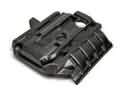 Toyota Highlander Engine Cover
 Toyota Highlander Cam Gear
 Toyota Highlander Crankshaft Pulley
 Toyota Highlander Crankshaft Seal
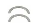 Toyota Highlander Crankshaft Thrust Washer
 Toyota Highlander Oil Pan
 Toyota Highlander Oil Pump
 Toyota Highlander Oil Pump Gasket
 Toyota Highlander Piston
 Toyota Highlander Piston Ring Set
 Toyota Highlander Timing Cover