×
ToyotaParts- Hello
- Login or Register
- Quick Links
- Live Chat
- Track Order
- Parts Availability
- RMA
- Help Center
- Contact Us
- Shop for
- Toyota Parts
- Scion Parts
My Garage
My Account
Cart
OEM 2001 Toyota Highlander Cylinder Head Gasket
Engine Cylinder Head Gasket- Select Vehicle by Model
- Select Vehicle by VIN
Select Vehicle by Model
orMake
Model
Year
Select Vehicle by VIN
For the most accurate results, select vehicle by your VIN (Vehicle Identification Number).
3 Cylinder Head Gaskets found


2001 Toyota Highlander Head Gasket
Part Number: 11115-28040$74.52 MSRP: $104.61You Save: $30.09 (29%)Ships in 1-3 Business DaysProduct Specifications- Other Name: Gasket, Cylinder Head; Engine Cylinder Head Gasket; Cylinder Head Gasket; Engine Gasket Set
- Replaces: 11115-28011, 11115-28010, 11115-28012, 11115-28013
- Part Name Code: 11115
- Item Weight: 0.70 Pounds
- Item Dimensions: 18.9 x 13.8 x 3.2 inches
- Condition: New
- Fitment Type: Direct Replacement
- SKU: 11115-28040
- Warranty: This genuine part is guaranteed by Toyota's factory warranty.

2001 Toyota Highlander Head Gasket
Part Number: 11116-20032$65.52 MSRP: $91.97You Save: $26.45 (29%)Ships in 1-3 Business DaysProduct Specifications- Other Name: Gasket, Cylinder Head; Engine Cylinder Head Gasket; Cylinder Head Gasket; Engine Gasket Set
- Replaces: 11116-20031, 11116-20030
- Part Name Code: 11116
- Item Weight: 1.40 Pounds
- Item Dimensions: 19.0 x 8.6 x 0.2 inches
- Condition: New
- Fitment Type: Direct Replacement
- SKU: 11116-20032
- Warranty: This genuine part is guaranteed by Toyota's factory warranty.
2001 Toyota Highlander Gasket, Cylinder Head
Part Number: 11115-20032$65.52 MSRP: $91.97You Save: $26.45 (29%)Ships in 1-3 Business DaysProduct Specifications- Other Name: Engine Cylinder Head Gasket; Engine Gasket Set; Head Gasket
- Replaces: 11115-20030, 11115-20031
- Part Name Code: 11115
- Item Weight: 1.40 Pounds
- Item Dimensions: 19.6 x 8.5 x 0.2 inches
- Condition: New
- Fitment Type: Direct Replacement
- SKU: 11115-20032
- Warranty: This genuine part is guaranteed by Toyota's factory warranty.
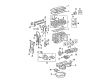
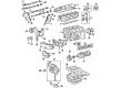
2001 Toyota Highlander Cylinder Head Gasket
Looking for affordable OEM 2001 Toyota Highlander Cylinder Head Gasket? Explore our comprehensive catalogue of genuine 2001 Toyota Highlander Cylinder Head Gasket. All our parts are covered by the manufacturer's warranty. Plus, our straightforward return policy and speedy delivery service ensure an unparalleled shopping experience. We look forward to your visit!
2001 Toyota Highlander Cylinder Head Gasket Parts Q&A
- Q: How to replace the cylinder head gasket on 2001 Toyota Highlander?A: The replacement of cylinder head gaskets requires initial fuel spill prevention by disconnecting the fuel pump connector then starting the engine before placing the ignition switch into LOCK (OFF) position. Finally, disconnect the negative (-) terminal cable from the battery followed by reconnecting the fuel pump connector. The procedure begins with removal of the front suspension brace sub-assembly [53607A], chain sub-assembly [13506 / 98-14] before draining coolant and transferring oil (4WD drive type) using new drain gaskets fitted with a torque of 49 Nm (500 kgf-cm, 36 ft. lbs.). Technical specialists must disconnect the radiator hose outlet [16572 / 98-20], union to check valve hose [44773F / 98-82], heater inlet water hose [87245 / 98-190] and fuel tube sub-assembly [23901 / 98-40]. The service technician should begin by removing the camshaft timing oil control valve assembly [11101 / 98-5] while employing Special Service Tools: 09520-01010, 09520-24010 (09520-32040) to separate the front drive shaft assembly RH (4WD drive type) [43410 / 98-68] as well as the engine mounting insulator assembly RR (4WD drive type) requires 2 bolt removal and the transverse engine mounting bracket (4WD drive type) [12321A / 98-10] has 6 bolts for separation. First disconnect two water bypass hoses then remove five bolts and two nuts in order to take out the intake manifold assembly together with its gasket. To proceed with this procedure you must remove the 2 bolts and nuts No. 1 and No. 2 from exhaust manifold stay and unfasten the 5 exhaust manifold nuts along with the gasket. The operations start with disassembling 2 bolts from engine wire [82121 / 98-151] before proceeding to take out intake manifold insulator No.1 [17135A / 98-26] and exhaust manifold heat insulator No.1 [17167 / 98-26] and exhaust manifold converter sub-assembly [25051 / 98-26]. Remove the No.2 camshaft [13512 / 98-14] and camshaft [13511 / 98-14] by taking off their bearing caps through the specified installation order. The removal of the camshaft bearing No.2 [11821 / 98-14] and cylinder head sub-assembly [11101 / 98-5] happens after performing uniform torque bolt loosening for ten cylinder head bolts in the correct sequence while ensuring washers stay inside the cylinder head. Measure the length of all head bolts with vernier calipers on cylinder head set bolt [11101A / 98-5] to replace bolts exceeding 164.2 mm (6.465 inch). Use a new cylinder head gasket [11115 / 98-5] by placing it stamp side up and check the surface for oil contamination before slowly installing the cylinder head to prevent gasket damage. Install the cylinder head sub-assembly [11101 / 98-5] by applying seal packing (Part No. 08826-00080 or equivalent) in a bead shape, ensuring to install the cylinder head within 3 minutes and tighten the cylinder head bolts within 15 minutes, applying a light coat of engine oil on the threads and under the heads of the bolts, then uniformly tighten the bolts to a torque of 79 Nm (806 kgf-cm, 58 ft. lbs.) and mark the front side of the cylinder head bolt with paint before retightening by 90 degrees in the specified sequence. First install camshaft [13511 / 98-14] then secure bearing caps No.1 and No.3 at 30 Nm (301 kgf-cm, 22 ft. lbs.) and 9.0 Nm (92 kgf-cm, 80 inch lbs.), respectively. After that, repeat the same torque recommendations with bearing caps No.2 and No.3 for camshaft [13512 / 98-14]. The exhaust manifold converter sub-assembly [25051 / 98-26] requires installation with a new gasket and 5 nuts at 37 Nm (378 kgf-cm, 27 ft. lbs.) torque rating before the technician installs the No.1 and No.2 exhaust manifold stay with 2 bolts and 2 nuts at 44 Nm (449 kgf-cm, 32 ft. lbs.) torque setting. Install the transverse engine mounting bracket (4WD drive type) [12321 A / 98-10] with 15 bolts, applying 34 Nm (347 kgf-cm, 25 ft. lbs.) for Bolt A and 64 Nm (653 kgf-cm, 47 ft. lbs.) for Bolt B, then install the engine mounting insulator assembly RR (4WD drive type) with bolts at 75 Nm (765 kgf-cm, 55 ft. lbs.), followed by the front drive shaft assembly RH (4WD drive type) [43410 / 98-68], camshaft timing oil control valve assembly [11101 / 98-5] at 9.0 Nm (92 kgf-cm, 80 inch lbs.), and connect the fuel tube sub-assembly [23901 / 98-40]. Install the chain sub-assembly [13506 / 98-14] using Special Service Tool: 09309-37010, then install the front suspension brace sub-assembly upper center [53607A] at 80 Nm (816 kgf-cm, 59 ft. lbs.), add engine oil, coolant, and transfer oil (4WD drive type) with a new gasket and filler plug at 49 Nm (500 kgf-cm, 36 ft. lbs.), and finally inspect for oil, coolant, and fuel leaks, check idle speed and ignition timing, inspect CO/HC, check ABS speed sensor signal, and inspect and adjust front wheel alignment.
Related 2001 Toyota Highlander Parts
 2001 Toyota Highlander Timing Belt
 2001 Toyota Highlander Timing Chain
 2001 Toyota Highlander Engine Mount
 2001 Toyota Highlander Camshaft
 2001 Toyota Highlander Camshaft Bearing
 2001 Toyota Highlander Crankshaft Pulley
 2001 Toyota Highlander Cylinder Head
 2001 Toyota Highlander Drain Plug
 2001 Toyota Highlander Intake Valve
 2001 Toyota Highlander Oil Pump
 2001 Toyota Highlander Piston
 2001 Toyota Highlander Timing Cover Gasket