×
ToyotaParts- Hello
- Login or Register
- Quick Links
- Live Chat
- Track Order
- Parts Availability
- RMA
- Help Center
- Contact Us
- Shop for
- Toyota Parts
- Scion Parts
My Garage
My Account
Cart
OEM 2002 Toyota Highlander Cylinder Head Gasket
Engine Cylinder Head Gasket- Select Vehicle by Model
- Select Vehicle by VIN
Select Vehicle by Model
orMake
Model
Year
Select Vehicle by VIN
For the most accurate results, select vehicle by your VIN (Vehicle Identification Number).
3 Cylinder Head Gaskets found


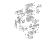
2002 Toyota Highlander Head Gasket
Part Number: 11115-28040$74.52 MSRP: $104.61You Save: $30.09 (29%)Ships in 1-3 Business DaysProduct Specifications- Other Name: Gasket, Cylinder Head; Engine Cylinder Head Gasket; Cylinder Head Gasket; Engine Gasket Set
- Replaces: 11115-28011, 11115-28010, 11115-28012, 11115-28013
- Part Name Code: 11115
- Item Weight: 0.70 Pounds
- Item Dimensions: 18.9 x 13.8 x 3.2 inches
- Condition: New
- Fitment Type: Direct Replacement
- SKU: 11115-28040
- Warranty: This genuine part is guaranteed by Toyota's factory warranty.

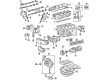
2002 Toyota Highlander Head Gasket
Part Number: 11116-20032$65.52 MSRP: $91.97You Save: $26.45 (29%)Ships in 1-3 Business DaysProduct Specifications- Other Name: Gasket, Cylinder Head; Engine Cylinder Head Gasket; Cylinder Head Gasket; Engine Gasket Set
- Replaces: 11116-20031, 11116-20030
- Part Name Code: 11116
- Item Weight: 1.40 Pounds
- Item Dimensions: 19.0 x 8.6 x 0.2 inches
- Condition: New
- Fitment Type: Direct Replacement
- SKU: 11116-20032
- Warranty: This genuine part is guaranteed by Toyota's factory warranty.
2002 Toyota Highlander Gasket, Cylinder Head
Part Number: 11115-20032$65.52 MSRP: $91.97You Save: $26.45 (29%)Ships in 1-3 Business DaysProduct Specifications- Other Name: Engine Cylinder Head Gasket; Engine Gasket Set; Head Gasket
- Replaces: 11115-20030, 11115-20031
- Part Name Code: 11115
- Item Weight: 1.40 Pounds
- Item Dimensions: 19.6 x 8.5 x 0.2 inches
- Condition: New
- Fitment Type: Direct Replacement
- SKU: 11115-20032
- Warranty: This genuine part is guaranteed by Toyota's factory warranty.
2002 Toyota Highlander Cylinder Head Gasket
Looking for affordable OEM 2002 Toyota Highlander Cylinder Head Gasket? Explore our comprehensive catalogue of genuine 2002 Toyota Highlander Cylinder Head Gasket. All our parts are covered by the manufacturer's warranty. Plus, our straightforward return policy and speedy delivery service ensure an unparalleled shopping experience. We look forward to your visit!
2002 Toyota Highlander Cylinder Head Gasket Parts Q&A
- Q: How to replace the cylinder head gasket on 2002 Toyota Highlander?A: The replacement process for the cylinder head gasket starts by stopping fuel leakage followed by removing the front suspension brace sub-assy upper center and the chain sub-assy. Next, drain the coolant and transfer oil (4WD drive type), add a new gasket and install the drain plug and torque to 49 Nm (500 kgf-cm, 36 ft. lbs.). Detach separate the radiator hose outlet from union to check valve hose together with heater inlet water hose along with fuel tube sub-assy before you remove camshaft timing oil control valve assy and front drive shaft assy RH for 4WD drive type using Special Service Tools: 09520-01010, 09520-24010 (09520-32040). Disconnect the engine mounting insulator assy RR (4WD drive type) through removing 2 bolts and subsequently disconnect the transverse engine mounting bracket (4WD drive type) by using 6 bolts for separation. The vehicle operator needs to remove the intake manifold by disconnecting two throttle body by-pass hoses then disassembling five bolts and two nuts to release the manifold and its gasket. The engine wire must be separated before removing intake manifold insulator No. 1 together with exhaust manifold heat insulator No. 1 and exhaust manifold converter sub-assy by dislodging 2 bolts, separating nuts No. 1 and No. 2 exhaust manifold stay, and discharging 5 nuts for exhaust manifold and gasket. Follow the sequence to remove the No. 2 camshaft bearing cap alongside the No. 3 one, before extracting the No. 2 camshaft and then proceeding to take off the No. 1 camshaft with its bearing cap. A 10 mm bi-hexagon wrench allows you to remove cylinder head sub-assy in the proper sequence by uniformly loosening 10 bolts which requires careful attention to prevent washers from dropping into the cylinder head because incorrect removal order may cause warpage or cracking of the head. Users should measure bolt lengths with a vernier caliper on the cylinder head set bolts before discarding any components which reach 164.2 mm (6.465 inch) in length. Install the new cylinder head gasket on the cylinder block surface having the Lot No. stamp facing upward. Clean all oil substance from the contact area before lowering the cylinder head gently to protect the gasket from damage. Apply seal packing (Part No. 08826-00080 or equivalent) as a bead shape before installing bolts and plate washers and torquing them to 79 Nm (806 kgf-cm, 58 ft. lbs.). The procedure requires marking the cylinder head bolt front side with paint followed by a second tightening at 90 degrees according to specified order. Start by installing the camshaft bearing cap No. 1 and No. 3 with a torque of 30 Nm (301 kgf-cm, 22 ft. lbs.) and No. 3 with 9.0 Nm (92 kgf-cm, 80 inch lbs.). Finish by installing No. 2 camshaft bearing cap No. 2 and No. 3 using the identical torque values. After using a new gasket to install the exhaust manifold converter sub-assy, torque the 5 nuts to 37 Nm (378 kgf-cm, 27 ft. lbs.) and then add the No. 1 and No. 2 exhaust manifold stay with 2 bolts and 2 nuts torqued to 44 Nm (449 kgf-cm, 32 ft. lbs.). The operator should start by installing the exhaust manifold heat insulator No. 1 with 12 Nm (122 kgf-cm, 9 ft. lbs.) torque before placing the intake manifold along with a fresh gasket and 5 bolts and 2 nuts torqued to 30 Nm (306 kgf-cm, 22 ft. lbs.). The transverse engine mounting bracket (4WD drive type) requires installation with six bolts which need torque control at 34 Nm (347 kgf-cm, 25 ft. lbs.) for Bolt A and 64 Nm (653 kgf-cm, 47 ft. lbs.) for Bolt B. Following this, the engine mounting insulator assy RR (4WD drive type) needs bolting and torquing to 75 Nm (765 kgf-cm, 55 ft. lbs.). Install the front drive shaft assy RH (4WD drive type) together with the camshaft timing oil control valve assy that requires 9.0 Nm (92 kgf-cm, 80 inch lbs.) torque along with the connection of fuel tube sub-assy while using Special Service Tool: 09309-37010 to install the chain sub-assy. Install the front suspension brace sub-assy upper center with 80 Nm torque (816 kgf-cm, 59 ft. lbs.) before adding engine oil and coolant and transfer oil (4WD drive type) with a new gasket for filling and using a 49 Nm torque (500 kgf-cm, 36 ft. lbs.) for the filler plug. Inspect for leaks and check idle speed, ignition timing, CO/HC, and ABS speed sensor signal before adjusting the front wheel.
Related 2002 Toyota Highlander Parts
 2002 Toyota Highlander Timing Belt
 2002 Toyota Highlander Timing Chain
 2002 Toyota Highlander Engine Mount
 2002 Toyota Highlander Camshaft
 2002 Toyota Highlander Camshaft Bearing
 2002 Toyota Highlander Crankshaft Pulley
 2002 Toyota Highlander Cylinder Head
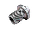 2002 Toyota Highlander Drain Plug
 2002 Toyota Highlander Intake Valve
 2002 Toyota Highlander Oil Pump
 2002 Toyota Highlander Piston
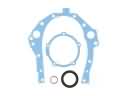 2002 Toyota Highlander Timing Cover Gasket