×
ToyotaParts- Hello
- Login or Register
- Quick Links
- Live Chat
- Track Order
- Parts Availability
- RMA
- Help Center
- Contact Us
- Shop for
- Toyota Parts
- Scion Parts
My Garage
My Account
Cart
OEM Scion Blower Motor
A/C Heater Blower Motor- Select Vehicle by Model
- Select Vehicle by VIN
Select Vehicle by Model
orMake
Model
Year
Select Vehicle by VIN
For the most accurate results, select vehicle by your VIN (Vehicle Identification Number).
10 Blower Motors found


Scion Blower Motor Part Number: 87103-02200
$138.64 MSRP: $196.26You Save: $57.62 (30%)Ships in 1-3 Business DaysProduct Specifications- Other Name: Motor Sub-Assembly, Blower; HVAC Blower Motor Assembly; Blower Assembly; Fan & Motor; Motor Sub-Assembly, Blower W/Fan; HVAC Blower Motor
- Manufacturer Note: AIR CONDITIONER-MANUAL
- Replaces: 87103-02280, 87103-42090


Scion Blower Motor, Upper Part Number: SU003-02079
$130.75 MSRP: $172.14You Save: $41.39 (25%)Ships in 1-3 Business DaysProduct Specifications- Other Name: Motor Assembly; HVAC Blower Motor Housing, Upper; HVAC Blower Motor; Motor Sub-Assembly, Blower W/Fan
- Position: Upper


Scion Blower Motor Part Number: 87103-42101
$163.55 MSRP: $231.52You Save: $67.97 (30%)Ships in 1 Business DayProduct Specifications- Other Name: Motor Sub-Assembly, Blower; HVAC Blower Motor Assembly; Blower Assembly; Fan & Motor; Motor Sub-Assembly, Blower W/Fan; HVAC Blower Motor
- Replaces: 87103-42100


Scion Blower Motor Part Number: 87103-52141
$141.58 MSRP: $200.42You Save: $58.84 (30%)Ships in 1-2 Business DaysProduct Specifications- Other Name: Motor Sub-Assembly, Blower; HVAC Blower Motor; Blower Assembly; Motor Sub-Assembly, Blower W/Fan
- Replaces: 87103-52140


Scion Blower Motor Part Number: 87103-20160
$171.54 MSRP: $242.83You Save: $71.29 (30%)Ships in 1-3 Business DaysProduct Specifications- Other Name: Motor Sub-Assembly, Blower; HVAC Blower Motor Assembly; Blower Assembly; Fan & Motor; Motor Sub-Assembly, Blower W/Fan; HVAC Blower Motor
- Replaces: 87103-20130

Scion Blower Motor Part Number: 87103-WB001
$170.67 MSRP: $241.60You Save: $70.93 (30%)Ships in 1-3 Business DaysProduct Specifications- Other Name: Motor Sub-Assembly, Blower; HVAC Blower Motor Assembly; Motor Sub-Assembly, Blower W/Fan

Scion Blower Motor Part Number: 87103-12070
$157.87 MSRP: $223.49You Save: $65.62 (30%)Ships in 1-3 Business DaysProduct Specifications- Other Name: Motor Sub-Assembly, Blower; HVAC Blower Motor Assembly; Fan & Motor; Motor Sub-Assembly, Blower W/Fan
Scion Blower Motor Part Number: 87103-21010
$192.80 MSRP: $275.27You Save: $82.47 (30%)Ships in 1-3 Business DaysProduct Specifications- Other Name: Motor Sub-Assembly, Blower; HVAC Blower Motor Assembly; Fan & Motor; Motor Sub-Assembly, Blower W/Fan

Scion Blower Motor Part Number: 87103-74031
$111.85 MSRP: $157.00You Save: $45.15 (29%)Ships in 1-2 Business DaysProduct Specifications- Other Name: Motor Sub-Assembly, Blower; HVAC Blower Motor Assembly; Blower Assembly; Motor Sub-Assembly, Blower W/Fan


Scion Blower Motor Part Number: 87103-52080
Product Specifications- Other Name: Motor Sub-Assembly, Blower; HVAC Blower Motor Assembly; Blower Assembly; Fan & Motor; Motor Sub-Assembly, Blower W/Fan; HVAC Blower Motor
- Manufacturer Note: COLD SPEC
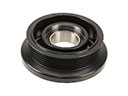
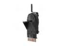
Scion Blower Motor
OEM parts deliver unmatched quality you can rely on. They pass extensive quality control inspections. Scion produces them to the official factory specifications. This process helps prevent defects and imperfections. So you can get exceptional lifespan and a flawless fit. Need new OEM Scion Blower Motor? You'll love our wide selection of genuine options. Shop in minutes and skip the hunt. Our prices are unbeatable, you'll save time and money. It's easy to shop and find the right piece. Our committed customer service team gives professional help from start to finish. Every part includes a manufacturer's warranty. We ship quickly, your parts will arrive fast at your door.
Scion Blower Motor forces cabin air in, which maintains stability in temperature all through the driving seasons. Scion was introduced in 2003, and it aimed at youthful drivers with bold contours, sunshine paint and the no-haggle price that is not a game changer. Every release was like a music drop, with Release Series runs that disappeared quickly and hooked the fans over the internet. Virtual Scion City allowed customers to design rides online then drive away the ride with the specifications and make the purchase just a simple online click. As the experimenter of Toyota, Scion experimented with weird colors, interchangeably compatible cabins, and new technology first, transforming more than 1,000,000 first-time buyers. Through its concepts of personalization, transparency, and low cost of entry, the badge continues to reverberate in contemporary car culture even after its retirement in 2016. Within any contemporary cabin of the badge above, the Blower Motor draws electrical juice, turns a balanced fan and blasts hot or cool air to glass, feet and faces. A multi-speed resistor allows the Blower Motor to skip between whisper and full blast in a couple of seconds, giving the driver actual control of comfort and clearing the windows before the humidity fogs up the vision. Toughened brushes and tightly fitted rotor ensure that the Blower Motor is non-squeaky in stop-and-go traffic, resistant to heat soak that burns lesser fans. Replacement of any Scion regains its sharp airflow, proving Blower Motor a simple upgrade with oversized rewards.
Scion Blower Motor Parts and Q&A
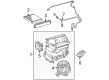
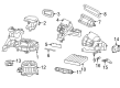
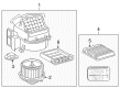
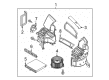
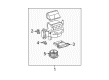
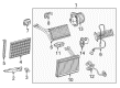
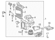
- Q: How to service and repair the blower motor on Scion tC?A:Service and repair of the blower motor requires starting with removal of the instrument panel sub-assembly upper w/front passenger Air Bag assembly before proceeding with the instrument panel lower assembly. The procedure to separate the blower assembly includes first removing the ECM and air duct followed by the step-by-step process of disconnecting the 3 connectors and unthreading 3 screws and a bolt before releasing the claw to free the assembly. After that detach the air filter case by unclipping its two claws followed by extracting the air inlet servomotor by loosening its two screws. To proceed detach the blower motor control that holds its position using 2 screws until you can separate the blower w/fan motor sub-assembly by removing 3 screws. Reinstall the blower assembly after you secure it by tightening the claw followed by the bolt accompanied by adjacent 3 screws while applying a torque of 9.8 N.m (100 kgf.cm, 87 in.lbf) to the bolt. The installation process requires placing back the instrument panel sub-assembly upper w/front passenger Air Bag assembly and instrument panel lower assembly last.
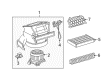
- Q: How to service and repair the blower motor on Scion xB?A:The first step for servicing the blower motor involves removing the air inlet control servo motor after unscrewing its two screws. Now you must unfasten the 2 claws until the air filter case can be taken out. The next step requires extraction of the clean air filter. Unscrew the 2 screws holding the blower resistor and use this as the final step to eliminate the blower motor sub-assembly through the extraction of its 3 screws.