×
ToyotaParts- Hello
- Login or Register
- Quick Links
- Live Chat
- Track Order
- Parts Availability
- RMA
- Help Center
- Contact Us
- Shop for
- Toyota Parts
- Scion Parts
My Garage
My Account
Cart
OEM Scion Axle Shaft
Car Axle Shaft- Select Vehicle by Model
- Select Vehicle by VIN
Select Vehicle by Model
orMake
Model
Year
Select Vehicle by VIN
For the most accurate results, select vehicle by your VIN (Vehicle Identification Number).
25 Axle Shafts found


Scion Axle Assembly, Rear Part Number: SU003-00785
$309.96 MSRP: $411.57You Save: $101.61 (25%)Ships in 1-3 Business DaysProduct Specifications- Other Name: Drive Shaft Assembly Rear 92205; CV Axle Assembly, Rear; GSP Cv Axle; Axle Shaft; Shaft Assembly, Rear Drive, Passenger Side; Shaft Assembly, Rear Drive, Driver Side; CV Axle Assembly
- Position: Rear


Scion Axle Assembly, Passenger Side Part Number: 43410-21100
$449.90 MSRP: $659.34You Save: $209.44 (32%)Ships in 1-3 Business DaysProduct Specifications- Other Name: Shaft Assembly, Front Drive; CV Axle Assembly, Front Right; GSP Cv Axle; Axle Shaft; Shaft Assembly, Front Drive, Passenger Side; CV Axle Assembly
- Position: Passenger Side


Scion Axle Assembly, Driver Side Part Number: 43420-44050
$364.10 MSRP: $533.59You Save: $169.49 (32%)Ships in 1-3 Business DaysProduct Specifications- Other Name: Shaft Assembly, Front Drive; CV Axle Assembly, Front Left; GSP Cv Axle; Axle Shaft; Shaft Assembly, Front Drive, Driver Side; CV Axle Assembly
- Position: Driver Side


Scion Axle Assembly, Driver Side Part Number: 43420-12700
$374.88 MSRP: $549.39You Save: $174.51 (32%)Ships in 1-3 Business DaysProduct Specifications- Other Name: Shaft Assembly, Front Drive; CV Axle Assembly, Front Left; GSP Cv Axle; Axle Shaft; Shaft Assembly, Front Drive, Driver Side; CV Axle Assembly
- Position: Driver Side

Scion Axle Assembly, Passenger Side Part Number: 43410-12760
$393.15 MSRP: $576.17You Save: $183.02 (32%)Ships in 1-3 Business DaysProduct Specifications- Other Name: Shaft Assembly, Front Drive; CV Axle Assembly, Front Right; GSP Cv Axle; Axle Shaft; Shaft Assembly, Front Drive, Passenger Side; CV Axle Assembly
- Position: Passenger Side

Scion Axle Assembly, Driver Side Part Number: 43420-0R082
$352.41 MSRP: $516.46You Save: $164.05 (32%)Ships in 1-3 Business DaysProduct Specifications- Other Name: Shaft Assembly, Front Drive; CV Axle Assembly, Front Left; GSP Cv Axle; Axle Shaft; Shaft Assembly, Front Drive, Driver Side; CV Axle Assembly
- Position: Driver Side
- Replaces: 43420-0R080, 43420-0R081
Scion Axle Assembly, Driver Side Part Number: 43420-21070
$442.87 MSRP: $649.02You Save: $206.15 (32%)Ships in 1-3 Business DaysProduct Specifications- Other Name: Shaft Assembly, Front Drive; CV Axle Assembly, Front Left; GSP Cv Axle; Axle Shaft; Shaft Assembly, Front Drive, Driver Side; CV Axle Assembly
- Position: Driver Side

Scion Axle Assembly, Driver Side Part Number: 43420-74050
$366.37 MSRP: $536.91You Save: $170.54 (32%)Ships in 1-3 Business DaysProduct Specifications- Other Name: Shaft Assembly, Front Drive; CV Axle Assembly, Front Left; GSP Cv Axle; Axle Shaft; Shaft Assembly, Front Drive, Driver Side; CV Axle Assembly
- Position: Driver Side

Scion Axle Assembly, Front Driver Side Part Number: 43420-52071
$370.23 MSRP: $542.57You Save: $172.34 (32%)Ships in 1-3 Business DaysProduct Specifications- Other Name: Shaft Assembly, Front Drive; CV Axle Assembly, Front Left; CV Axle Assembly; GSP Cv Axle; Axle Shaft
- Position: Front Driver Side
- Replaces: 43420-52070
Scion Axle Assembly, Front Driver Side Part Number: 43420-44041
$375.22 MSRP: $549.89You Save: $174.67 (32%)Ships in 1-3 Business DaysProduct Specifications- Other Name: Shaft Assembly, Front Drive; CV Axle Assembly, Front Left; CV Axle Assembly; GSP Cv Axle; Axle Shaft
- Position: Front Driver Side
- Replaces: 43420-44040
Scion Axle Assembly, Passenger Side Part Number: 43410-74060
$412.90 MSRP: $605.12You Save: $192.22 (32%)Ships in 1-3 Business DaysProduct Specifications- Other Name: Shaft Assembly, Front Drive; CV Axle Assembly, Front Right; GSP Cv Axle; Axle Shaft; Shaft Assembly, Front Drive, Passenger Side; CV Axle Assembly
- Position: Passenger Side

Scion Axle Assembly, Passenger Side Part Number: 43410-52250
$412.90 MSRP: $605.12You Save: $192.22 (32%)Ships in 1-3 Business DaysProduct Specifications- Other Name: Shaft Assembly, Front Drive; CV Axle Assembly, Front Right; GSP Cv Axle; Axle Shaft; Shaft Assembly, Front Drive, Passenger Side; CV Axle Assembly
- Position: Passenger Side

Scion Axle Assembly, Front Passenger Side Part Number: 43410-52071
$414.04 MSRP: $606.77You Save: $192.73 (32%)Ships in 1-3 Business DaysProduct Specifications- Other Name: Shaft Assembly, Front Drive; CV Axle Assembly, Front Left, Front Right; Axle Shaft
- Position: Front Passenger Side
- Replaces: 43410-52070

Scion Axle Assembly, Front Driver Side Part Number: 43420-12761
$442.87 MSRP: $649.02You Save: $206.15 (32%)Ships in 1-3 Business DaysProduct Specifications- Other Name: Shaft Assembly, Front Drive; CV Axle Assembly, Front Left; CV Axle Assembly; GSP Cv Axle; Axle Shaft
- Position: Front Driver Side
- Replaces: 43420-12760
Scion Axle Assembly, Front Passenger Side Part Number: 43410-12821
$433.67 MSRP: $635.56You Save: $201.89 (32%)Ships in 1-3 Business DaysProduct Specifications- Other Name: Shaft Assembly, Front Drive; CV Axle Assembly, Front Right; CV Axle Assembly; GSP Cv Axle; Axle Shaft
- Position: Front Passenger Side
- Replaces: 43410-12820
Scion Axle Assembly, Front Passenger Side Part Number: 43410-21111
$446.95 MSRP: $655.02You Save: $208.07 (32%)Ships in 1-3 Business DaysProduct Specifications- Other Name: Shaft Assembly, Front Drive; CV Axle Assembly, Front Right; CV Axle Assembly; GSP Cv Axle; Axle Shaft
- Position: Front Passenger Side
- Replaces: 43410-21110
Scion Axle Assembly, Front Passenger Side Part Number: 43410-44042
$469.54 MSRP: $688.11You Save: $218.57 (32%)Ships in 1-3 Business DaysProduct Specifications- Other Name: Shaft Assembly, Front Drive; CV Axle Assembly, Front Right; CV Axle Assembly; GSP Cv Axle; Axle Shaft
- Position: Front Passenger Side
- Replaces: 43410-44041, 43410-44040

Scion Axle Assembly, Driver Side Part Number: 43420-WB003
$570.16 MSRP: $835.58You Save: $265.42 (32%)Ships in 1-3 Business DaysProduct Specifications- Other Name: Shaft Assembly, Front Drive; CV Axle Assembly, Front Left; GSP Cv Axle; Axle Shaft; Shaft Assembly, Front Drive, Driver Side; CV Axle Assembly
- Position: Driver Side
- Replaces: 43420-WB001
Scion Axle Assembly, Driver Side Part Number: 43420-WB004
$662.24 MSRP: $970.51You Save: $308.27 (32%)Ships in 1-3 Business DaysProduct Specifications- Other Name: Shaft Assembly, Front Drive; CV Axle Assembly, Front Left; Axle Shaft; Shaft Assembly, Front Drive, Driver Side
- Position: Driver Side
- Replaces: 43420-WB002

Scion Axle Assembly, Passenger Side Part Number: 43410-WB003
$730.07 MSRP: $1069.93You Save: $339.86 (32%)Ships in 1-3 Business DaysProduct Specifications- Other Name: Shaft Assembly, Front Drive; CV Axle Assembly, Front Right; GSP Cv Axle; Axle Shaft; Shaft Assembly, Front Drive, Passenger Side; CV Axle Assembly
- Position: Passenger Side
- Replaces: 43410-WB001
| Page 1 of 2 |Next >
1-20 of 25 Results
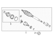
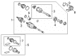
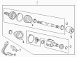
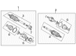
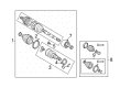
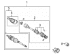
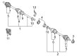
Scion Axle Shaft
OEM parts deliver unmatched quality you can rely on. They pass extensive quality control inspections. Scion produces them to the official factory specifications. This process helps prevent defects and imperfections. So you can get exceptional lifespan and a flawless fit. Need new OEM Scion Axle Shaft? You'll love our wide selection of genuine options. Shop in minutes and skip the hunt. Our prices are unbeatable, you'll save time and money. It's easy to shop and find the right piece. Our committed customer service team gives professional help from start to finish. Every part includes a manufacturer's warranty. We ship quickly, your parts will arrive fast at your door.
The Scion Axle Shaft is a direct transfer of engine torque to the wheels which maintains power delivery by being crisp. In 2003, Scion hit the streets with compact cars with one basic trim, bright colors, and a dare to customize, a welcome change to the giant option lists that clogged the car dealership showrooms of the competitors. Scion disregarded stale billboards and created an online city, hosting parties both on and offline, to reach a crowd of people who despised spin, yet adored limited Release Series drops. Scion was Toyota's guinea pig, testing new ideas of sales and technology as well as drawing first-time buyers into the family without preaching pedigree. Scion could have died in 2016 but one million owners continue to boast of the no-nonsense buying experience and the young cool attitude of the brand. High tensile steel Axle Shaft rotating force is delivered to the hub through splines on the axle by the differential, and constant speed joint flex is prevented by a high-tensile steel axle. The Axle Shaft also bears some weight in the vehicle, corrects slight misalignment, and makes traction control content by ensuring that each wheel turns precisely at the direction the sensors require even during situations where potholes force the suspension travel to unnatural angles. The Axle Shaft is long-lived when its joints remain greased and boots in place, as due to wear, vibration becomes apparent and power loss ensues shortly.
Scion Axle Shaft Parts and Q&A
- Q: How to install the axle shaft assembly on the LH and RH sides on Scion tC?A:The installation procedure for LH front drive shaft assembly starts with gear oiling the inboard joint shaft spline followed by proper spline alignment before driving the shaft in using a brass bar assisted by a hammer to keep the snap ring opening pointed downward but protect oil seal and boot while guarding the dust cover from damage. The front drive shaft installation for the RH side requires gear oil coating of the spline followed by alignment before driving in the shaft with two bolts tightened to 64 Nm (650 kgf-cm, 47 ft-lbf). Move on by matching each mark before putting in the drive shaft to the front axle while ensuring protection for both the outboard joint boot and speed sensor rotor. The front No. 1 suspension lower arm sub-assembly needs the lower ball joint to be installed onto the suspension lower arm by using a bolt with 2 nuts and reaching a torque of 89 Nm (908 kgf-cm, 66 ft-lbf). Install a new nut to the tie rod end before mounting it to the steering knuckle where a final torque of 49 Nm (500 kgf-cm, 36 ft-lbf) should be achieved. After that, add a new cotter pin by tightening the nut 60 degrees to compensate for misalignment between holes. The speed sensor front needs installation to the steering knuckle using a bolt with 8.0 Nm (82 kgf-cm, 71 in-lbf) torque strength. Connect the speed sensor wire along with the flexible hose to the shock absorber through a bolt that should receive 19 Nm (194 kgf-cm, 14 ft-lbf) torque. Keep the speed sensor undamaged and prevent the attachment of foreign matter to the sensor. The installation of the front stabilizer link requires use of a 6 mm hexagon wrench to stabilize the ball joint while torquing its nut to 74 Nm (755 kgf-cm, 55 ft-lbf). Apply a non-residue solvent to wash threaded drive shaft and axle hub nut components before installing a new axle hub nut torqued to 216 Nm (2200 kgf-cm, 159 ft-lbf) then stake the nut by hammering on a chisel. The engine installation process requires front wheel torque of 103 Nm (1050 kgf-cm, 76 ft-lbf) with automatic transaxle fluid addition followed by fluid inspection adjustments before manual transaxle oil addition and front wheel alignment inspection and adjustment before checking the ABS speed sensor signal.
- Q: How to install the axle shaft assembly and related components on Scion xB?A:Begin the front drive shaft installation on the LH side by using a brass bar with a hammer to align the drive shaft splines before applying automatic transaxle fluid on inboard joint shaft splines if using an automatic transaxle or manual transaxle gear oil for a manual transaxle. Set the snap ring with its opening facing downward yet maintain protection of oil seals and boots as well as the dust cover. Proceed by aligning shaft splines on the right side before installing the drive shaft with two bolts that require 64 Nm torque (650 kgf-cm or 47 ft-lbf) and applying correct spline coating while avoiding damage to all components. The installation of the front axle assembly LH requires matchmark alignment followed by mounting it onto the front steering knuckle with axle hub while preventing excessive steering knuckle extension and verifying the speed sensor rotor cleanliness and protecting the oil seal and drive shaft boot and speed sensor rotor. Apply this installation method for the RH front side. The installation process for the front lower No. 1 suspension arm sub-assemblies LH and RH along with the tie rod end sub-assemblies LH and RH and front stabilizer link assemblies LH and RH must be performed according to the same sequence on both sides. Tighten the front speed sensors LH and RH as well as the front axle hub nuts LH and RH and the front wheel to 103 Nm (1,050 kgf-cm, 76 ft-lbf). For the automatic transaxle vehicles add automatic transaxle fluid while manual transaxle vehicles require manual transaxle oil. After filling the appropriate fluid inspect both systems for leakage. The process ends with evaluation of front wheel alignment and examination of ABS speed sensor signals before placing rear engine under covers LH and RH and the No. 1 engine under cover installation.