×
ToyotaParts- Hello
- Login or Register
- Quick Links
- Live Chat
- Track Order
- Parts Availability
- RMA
- Help Center
- Contact Us
- Shop for
- Toyota Parts
- Scion Parts
My Garage
My Account
Cart
OEM Scion tC Axle Shaft
Car Axle Shaft- Select Vehicle by Model
- Select Vehicle by VIN
Select Vehicle by Model
orMake
Model
Year
Select Vehicle by VIN
For the most accurate results, select vehicle by your VIN (Vehicle Identification Number).
8 Axle Shafts found


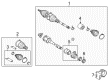
Scion tC Axle Assembly, Passenger Side Part Number: 43410-21100
$449.90 MSRP: $659.34You Save: $209.44 (32%)Ships in 1-3 Business Days

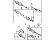
Scion tC Axle Assembly, Driver Side Part Number: 43420-44050
$364.10 MSRP: $533.59You Save: $169.49 (32%)Ships in 1-3 Business Days
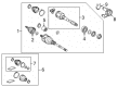
Scion tC Axle Assembly, Driver Side Part Number: 43420-0R082
$352.41 MSRP: $516.46You Save: $164.05 (32%)Ships in 1-3 Business DaysScion tC Axle Assembly, Driver Side Part Number: 43420-21070
$442.87 MSRP: $649.02You Save: $206.15 (32%)Ships in 1-3 Business DaysScion tC Axle Assembly, Front Driver Side Part Number: 43420-44041
$375.22 MSRP: $549.89You Save: $174.67 (32%)Ships in 1-3 Business DaysScion tC Axle Assembly, Front Passenger Side Part Number: 43410-21111
$446.95 MSRP: $655.02You Save: $208.07 (32%)Ships in 1-3 Business DaysScion tC Axle Assembly, Front Passenger Side Part Number: 43410-44042
$469.54 MSRP: $688.11You Save: $218.57 (32%)Ships in 1-3 Business Days
Scion tC Outer Joint Assembly, Driver Side Part Number: 43470-80167
$212.20 MSRP: $302.98You Save: $90.78 (30%)Ships in 1-3 Business Days
Scion tC Axle Shaft
Choose genuine Axle Shaft that pass strict quality control tests. You can trust the top quality and lasting durability. Shopping for OEM Axle Shaft for your Scion tC? Our website is your one-stop destination. We stock an extensive selection of genuine Scion tC parts. The price is affordable so you can save more. It only takes minutes to browse and find the exact fit. Easily add to cart and check out fast. Our hassle-free return policy will keep you stress-free. We process orders quickly for swift delivery. Your parts will arrive faster, so you can get back on the road sooner.
Scion tC Axle Shaft is a very important part that greatly improves the trust and quality of the Scion tC, a compact car renowned for its fantastic handling. This Axle Shaft is very crucial in transferring power from the differential to the drive wheels together with the power that controls the tractions and handling more so during cornering. Made from chrome-molybdenum or carbon steel the Scion tC Axle Shaft gives excellent performance, efficiency and safety for driving a car. The versatility and the necessity of this model range is proven by the compatibility with different tC models, manufactured from 2005 to 2016. Thus, the Axle Shaft has the capacity to rotate in a different manner such that it has different speeds when the vehicle is making a turn which is good for giving the vehicle the much needed stability as well as improving the kind of ride that is offered by the vehicle. Also, the tC has high-end suspensions, the MacPherson strut front and the double-wishbone rear that combines well with Axle Shaft to support the car during its use. The Scion tC Axle Shaft sets it apart from other cars in the market because of not only the rock-solid construction but also because of the performance tuned engineering of the shaft. In summary, the Scion tC Axle Shaft is vital to keeping the car's driveline system in check, which in return makes the Scion tC to remain a fun and dependable car to drive.
Scion tC Axle Shaft Parts and Q&A
- Q: How to remove the axle shaft assembly on Scion tC?A:Your first step for front drive shaft assembly removal requires you to drain automatic transaxle fluid along with manual transaxle oil. Start by removing the front wheel as well as the engine under cover followed by removing the front axle hub nut through the use of Special Service Tool: 09930-00010 while gently striking the nut with a hammer until the nut unstakes completely. The front stabilizer link assembly requires removal of its nut while you use a 6 mm hexagon wrench to support the stud when the Ball Joint turns. You can safely dismantle the front Speed Sensor by removing its wire along with flexible hose from the Shock Absorber before disconnecting it from the steering knuckle. The maintenance requires the use of Special Service Tool: 09628-00011 while removing the cotter pin and nut before disconnecting the tie rod end sub-assembly. You can separate the front suspension lower arm from its lower ball joint through the removal of both the bolt and two nuts. Start by marking both the drive shaft and axle hub before using a plastic-faced hammer to disconnect the drive shaft from the hub while taking precautions for speed sensor rotor and boot protection. Use Special Service Tools 09520-01010 and 09520-24010 and 09520-32040 to remove the front drive shaft assembly by preserving the inboard joint boot and transaxle case oil seal and drive shaft dust cover and drive assembly. Each right-side bolt should be removed before you can pull out the drive shaft along with its bearing case. The removal process requires extra care to avoid damaging the inboard joint boot or dust cover. Vehicle weight on the hub bearing requires the use of Special Service Tool: 09608-16042, 09608-02021, or 09608-02041 and proper support to prevent any damage.
- Q: How to install the axle shaft assembly on the LH and RH sides on Scion tC?A:Before inserting the front drive shaft assembly on the LH side you need to apply gear oil on the inboard joint shaft spline followed by driving the shaft into position with a brass bar and hammer while orienting the snap ring opening towards the bottom to protect the oil seal alongside boot and dust cover. Recoating the spline of the inboard joint shaft follows before inserting the drive shaft and securing it with 2 bolts to 64 Nm (650 kgf-cm, 47 ft-lbf) tightening while protecting the oil seal, boot, and dust cover from damage. Fitting the drive shaft to the front axle requires matchmark alignment while taking care to avoid harming boot components of outboard joints and rotor Speed Sensors. The installation of the front No. 1 suspension lower arm sub-assembly requires attaching the lower Ball Joint to the suspension lower arm by using bolts and nuts which need torquing to 89 Nm (908 kgf-cm, 66 ft-lbf). Install the steering knuckle tie rod end by tightening a nut to 49 Nm at 500 kgf-cm or 36 ft-lbf and follow with a new cotter pin that requires extra tightening of 60 degrees when the holes are misaligned. When inserting the front speed sensor into the steering knuckle apply a bolt with torque set to 8.0 Nm (82 kgf-cm, 71 in-lbf). Route the speed sensor wire together with its flexible hose to the Shock Absorber while securing it with a bolt torqued to 19 Nm (194 kgf-cm, 14 ft-lbf). Installation should avoid damaging the speed sensor and preventing foreign matter from adhering to it and keep the sensor wire untwisted. When installing the front stabilizer link involve using a 6mm hexagon wrench to maintain ball joint stability and attach the nut which requires torque to 74 Nm (755 kgf-cm, 55 ft-lbf). Secure the new axle hub nut by tightening it to 216 Nm (2200 kgf-cm, 159 ft-lbf) using a non-residue solvent to clean the threaded drive shaft parts. Finish by chiseling the axle hub nut stake with a hammer. Put the engine under the engine compartment and tighten the front wheel to 103 Nm (1050 kgf-cm, 76 ft-lbf). Add automatic transaxle fluid while checking and adjusting it if required. The procedure for manual transaxle includes oil addition and appropriate inspection steps. The professional service concludes with assessments of the front wheel alignment along with testing of the ABS speed sensor signal.


Related Scion tC Parts
 Scion tC Control Arm
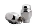 Scion tC Lug Nuts
 Scion tC CV Boot
 Scion tC Shock Absorber
 Scion tC Crossmember Bushing
 Scion tC CV Joint
 Scion tC Rear Crossmember
 Scion tC Shock and Strut Boot
 Scion tC Spare Wheel
 Scion tC Strut Mounts
 Scion tC Sway Bar Bushing
 Scion tC Sway Bar Link
Browse Scion tC Axle Shaft by Years
2016
2015
2014
2013
2012
2011
2010
2009
2008
2007
2006
2005