×
ToyotaParts- Hello
- Login or Register
- Quick Links
- Live Chat
- Track Order
- Parts Availability
- RMA
- Help Center
- Contact Us
- Shop for
- Toyota Parts
- Scion Parts
My Garage
My Account
Cart
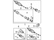
OEM 2007 Scion tC Axle Shaft
Car Axle Shaft- Select Vehicle by Model
- Select Vehicle by VIN
Select Vehicle by Model
orMake
Model
Year
Select Vehicle by VIN
For the most accurate results, select vehicle by your VIN (Vehicle Identification Number).
3 Axle Shafts found


2007 Scion tC Axle Assembly, Driver Side
Part Number: 43420-44050$353.43 MSRP: $517.96You Save: $164.53 (32%)Ships in 1-3 Business DaysProduct Specifications- Other Name: Shaft Assembly, Front Drive; CV Axle Assembly, Front Left; GSP Cv Axle; Axle Shaft; Shaft Assembly, Front Drive, Driver Side; CV Axle Assembly
- Position: Driver Side
- Part Name Code: 43420
- Item Weight: 17.90 Pounds
- Item Dimensions: 31.2 x 6.2 x 6.2 inches
- Condition: New
- Fitment Type: Direct Replacement
- SKU: 43420-44050
- Warranty: This genuine part is guaranteed by Toyota's factory warranty.
2007 Scion tC Axle Assembly, Front Driver Side
Part Number: 43420-44041$369.66 MSRP: $541.74You Save: $172.08 (32%)Ships in 1-3 Business DaysProduct Specifications- Other Name: Shaft Assembly, Front Drive; CV Axle Assembly, Front Left; CV Axle Assembly; GSP Cv Axle; Axle Shaft
- Position: Front Driver Side
- Replaces: 43420-44040
- Condition: New
- SKU: 43420-44041
- Warranty: This genuine part is guaranteed by Toyota's factory warranty.
2007 Scion tC Axle Assembly, Front Passenger Side
Part Number: 43410-44042$469.54 MSRP: $688.11You Save: $218.57 (32%)Ships in 1-3 Business DaysProduct Specifications- Other Name: Shaft Assembly, Front Drive; CV Axle Assembly, Front Right; CV Axle Assembly; GSP Cv Axle; Axle Shaft
- Position: Front Passenger Side
- Replaces: 43410-44041, 43410-44040
- Item Weight: 36.80 Pounds
- Item Dimensions: 29.9 x 6.1 x 6.2 inches
- Condition: New
- SKU: 43410-44042
- Warranty: This genuine part is guaranteed by Toyota's factory warranty.
2007 Scion tC Axle Shaft
Looking for affordable OEM 2007 Scion tC Axle Shaft? Explore our comprehensive catalogue of genuine 2007 Scion tC Axle Shaft. All our parts are covered by the manufacturer's warranty. Plus, our straightforward return policy and speedy delivery service ensure an unparalleled shopping experience. We look forward to your visit!
2007 Scion tC Axle Shaft Parts Q&A
- Q: How to service and repair the axle shaft components on 2007 Scion tC?A: When servicing front drive shaft components start with a proper fluid drain according to the manual or automatic transaxle type. Apply SST 09930-00010 along with a hammer to unstake the front axle hub nut yet maintain the drive shaft screw unharmed by ensuring total loosening of the staked part. Obtain the lock axle hub nut after you apply the brake system. To disconnect the front stabilizer link assembly you should remove the assembly nut and use a 6 mm hexagon wrench to stabilize the stud if the ball joint movement occurs. To begin disconnect the front speed sensor by removing its bolt while safeguarding the wire from damage after which use SST 09628-00011 for the tie rod end sub-assembly removal. Manipulate the front No. 1 suspension lower arm sub-assembly apart from the lower ball joint to remove it. The procedure to separate drive shaft from axle hub starts by documenting their positions before applying a plastic-faced hammer across the mark points. Perform this operation gently to avoid breaking the boot and speed sensor rotor. For both left and right front drive shaft assembly removal use SST 09520-01010, 09520-24010 (09520-32040) to detach the two bolts before pulling out with bearing case by maintaining the inboard joint boot and dust cover's protection. The front axle assembly requires support by using SST 09608-16042 (09608-02021, 09608-02041) to avoid hub bearing damage when needed. The disassembly process begins by removing the front No. 2 axle inboard joint boot clamp with a screwdriver or needle-nose pliers before extracting the inboard joint boot and assembly by marking joints to prevent using punches on the marks. Start by removing the front drive shaft damper and also the front No. 2 axle outboard joint boot clamp. Then remove the boot and all present grease before proceeding further. Use SST 09950-00020 together with SST 09950-00020 to remove front drive shaft hole snap ring along with dust covers before pressing out the bearing case with SST 09527-10011. Before installing the apparatus utilize SST 09950-60020 (09951-00710) to press in a new drive shaft bearing then add the bearing case snap ring followed by the bearing case installation through SST 09527-10011 until the bearing achieves complete insertion. Replace the dust covers while checking for any damage and put on the outboard joint boot combined with clamps while adding grease for lubrication. Reassemble the inboard joint assembly by placing it into the front drive shaft while aligning the matchmarks with correct directional orientation. To finish the installation you should bolt the front drive shaft assemblies at 64 Nm (650 kgf-cm, 47 ft. lbs.) and join both the front axle assembly before tightening the lower arm and tie rod end with their recommended torque specifications. Place the speed sensor and stabilizer link and axle hub nut back into position before you reassemble the engine under cover and front wheel. Only do this after proper inspection of appropriate transaxle fluids and adjusting the front wheel alignment and ABS speed sensor signal when needed.
Related 2007 Scion tC Parts
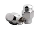 2007 Scion tC Lug Nuts
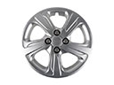 2007 Scion tC Wheel Cover
 2007 Scion tC CV Boot
 2007 Scion tC Coil Springs
 2007 Scion tC Shock Absorber
 2007 Scion tC Bump Stop
 2007 Scion tC CV Joint
 2007 Scion tC Crossmember Bushing
 2007 Scion tC Rear Crossmember
 2007 Scion tC Steering Knuckle
 2007 Scion tC Suspension Strut Rod
 2007 Scion tC Sway Bar Bracket