×
ToyotaParts- Hello
- Login or Register
- Quick Links
- Live Chat
- Track Order
- Parts Availability
- RMA
- Help Center
- Contact Us
- Shop for
- Toyota Parts
- Scion Parts
My Garage
My Account
Cart
OEM 2008 Toyota Highlander Crankshaft Position Sensor
Engine Crankshaft Position Sensor- Select Vehicle by Model
- Select Vehicle by VIN
Select Vehicle by Model
orMake
Model
Year
Select Vehicle by VIN
For the most accurate results, select vehicle by your VIN (Vehicle Identification Number).
4 Crankshaft Position Sensors found


2008 Toyota Highlander Sensor, Camshaft Position
Part Number: 90080-19014$69.78 MSRP: $83.30You Save: $13.52 (17%)Ships in 1-2 Business DaysProduct Specifications- Other Name: Sensor, Crank Position; Cam Position; Engine Camshaft; Crankshaft; RPM Sensor
- Replaces: 90919-05026
- Item Weight: 0.50 Pounds
- Item Dimensions: 4.0 x 2.8 x 2.1 inches
- Condition: New
- Fitment Type: Direct Replacement
- SKU: 90080-19014
- Warranty: This genuine part is guaranteed by Toyota's factory warranty.


2008 Toyota Highlander Camshaft Position Sensor, Driver Side
Part Number: 90919-T5005$102.96 MSRP: $144.53You Save: $41.57 (29%)Ships in 1-3 Business DaysProduct Specifications- Other Name: Sensor, Crank Position; Engine Camshaft Position Sensor, Left; Crankshaft Position Sensor; Camshaft Sensor; Cam Sensor; Sensor, Cam Position; Engine Camshaft Position Sensor
- Manufacturer Note: (L)
- Position: Driver Side
- Replaces: 9004A-19003, 90919-05060, 90919-T5002
- Part Name Code: 11101E
- Condition: New
- Fitment Type: Direct Replacement
- Require Quantity: 3
- SKU: 90919-T5005
- Warranty: This genuine part is guaranteed by Toyota's factory warranty.


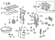
2008 Toyota Highlander Crankshaft Position Sensor
Part Number: 90080-19009$81.87 MSRP: $114.92You Save: $33.05 (29%)Ships in 1-2 Business DaysProduct Specifications- Other Name: Sensor, Crank Position; Engine Crankshaft Position Sensor; RPM Sensor, Engine Management; Crankshaft Sensor
- Manufacturer Note: (L)
- Replaces: 90919-05012
- Part Name Code: 15100R
- Item Weight: 0.50 Pounds
- Item Dimensions: 1.6 x 2.2 x 3.4 inches
- Condition: New
- Fitment Type: Direct Replacement
- SKU: 90080-19009
- Warranty: This genuine part is guaranteed by Toyota's factory warranty.


2008 Toyota Highlander Sensor, Crank Position
Part Number: 90919-A5003$72.15 MSRP: $101.28You Save: $29.13 (29%)Ships in 1-3 Business DaysProduct Specifications- Other Name: Engine Crankshaft Position Sensor; Crankshaft Position Sensor
- Manufacturer Note: (L)
- Replaces: 90919-05057
- Part Name Code: 11401G
- Item Weight: 0.40 Pounds
- Item Dimensions: 4.9 x 2.8 x 2.0 inches
- Condition: New
- Fitment Type: Direct Replacement
- SKU: 90919-A5003
- Warranty: This genuine part is guaranteed by Toyota's factory warranty.
2008 Toyota Highlander Crankshaft Position Sensor
Looking for affordable OEM 2008 Toyota Highlander Crankshaft Position Sensor? Explore our comprehensive catalogue of genuine 2008 Toyota Highlander Crankshaft Position Sensor. All our parts are covered by the manufacturer's warranty. Plus, our straightforward return policy and speedy delivery service ensure an unparalleled shopping experience. We look forward to your visit!
2008 Toyota Highlander Crankshaft Position Sensor Parts Q&A
- Q: How to install the crankshaft position sensor and related components on 2008 Toyota Highlander?A: The crankshaft position sensor installation requires you to apply engine oil on its O-ring followed by bolt attachment with a torque setting at 10 Nm (102 kgf-cm, 7 ft-lbf) and connector assembly. Begin by tightening the compressor and magnetic clutch only briefly and proceed to install both components. Reposition both suction hose sub-assembly and discharge hose sub-assembly to enable the connection. The work begins by adding together the radiator assembly along with fan assembly with motor and the cooler condenser assembly and upper radiator support sub-assembly. The hood lock assembly installation should be performed with the engine hood courtesy switch if it is present or without the switch then install the radiator grille. The cooling fan ECU connector should be connected with the oil cooler hose and both No. 2 and No. 1 radiator hoses. The installation process includes No. 1 air cleaner inlet together with No. 2 air cleaner inlet and battery before completing with the cool air intake duct seal. Start by adding recommissioning refrigerant through the system while checking for any leakage of engine coolant. Check the transaxle automatic fluid while inspecting for any evidence of oil leakage. A proper inspection of refrigerant leaks requires vehicle engine operation with a warmup phase. You should install No. 1 engine under cover together with the engine under cover assembly and the V-bank cover sub-assembly.
Related 2008 Toyota Highlander Parts
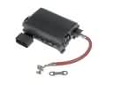 2008 Toyota Highlander Fuse Box
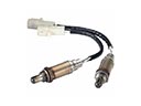 2008 Toyota Highlander Oxygen Sensor
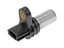 2008 Toyota Highlander Camshaft Position Sensor
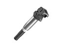 2008 Toyota Highlander Ignition Coil
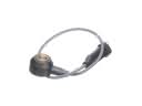 2008 Toyota Highlander Knock Sensor
 2008 Toyota Highlander Spark Plug
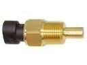 2008 Toyota Highlander Coolant Temperature Sensor
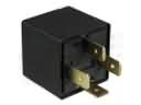 2008 Toyota Highlander Daytime Running Light Relay
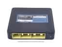 2008 Toyota Highlander Engine Control Module
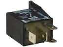 2008 Toyota Highlander Headlight Relay
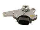 2008 Toyota Highlander Neutral Safety Switch
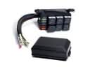 2008 Toyota Highlander Relay Block