×
ToyotaParts- Hello
- Login or Register
- Quick Links
- Live Chat
- Track Order
- Parts Availability
- RMA
- Help Center
- Contact Us
- Shop for
- Toyota Parts
- Scion Parts
My Garage
My Account
Cart
OEM Toyota Sienna Starter Motor
Starter Ignition- Select Vehicle by Model
- Select Vehicle by VIN
Select Vehicle by Model
orMake
Model
Year
Select Vehicle by VIN
For the most accurate results, select vehicle by your VIN (Vehicle Identification Number).
4 Starter motors found


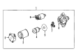
Toyota Sienna Starter
Part Number: 28100-0V012$217.61 MSRP: $310.69You Save: $93.08 (30%)Ships in 1-3 Business Days
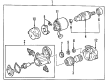
Toyota Sienna Starter Assembly
Part Number: 28100-74260-84$158.04 MSRP: $222.38You Save: $64.34 (29%)Ships in 1-3 Business Days
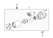
Toyota Sienna Starter
Part Number: 28100-0A011-84$160.01 MSRP: $225.18You Save: $65.17 (29%)Ships in 1-3 Business Days
Toyota Sienna Starter
Part Number: 28100-0P110$242.77 MSRP: $346.63You Save: $103.86 (30%)Ships in 1-2 Business Days
Toyota Sienna Starter Motor
Choose genuine Starter Motor that pass strict quality control tests. You can trust the top quality and lasting durability. Shopping for OEM Starter Motor for your Toyota Sienna? Our website is your one-stop destination. We stock an extensive selection of genuine Toyota Sienna parts. The price is affordable so you can save more. It only takes minutes to browse and find the exact fit. Easily add to cart and check out fast. Our hassle-free return policy will keep you stress-free. We process orders quickly for swift delivery. Your parts will arrive faster, so you can get back on the road sooner.
Toyota Sienna Starter Motor Parts and Q&A
- Q: How to remove the starter motor on Toyota Sienna?A:The battery should be disconnected first before starter motor removal. Start the procedure by removing the air cleaner inlet which leads to the No. 2 position and then remove the air cleaner cap sub-assembly along with the air cleaner filter element and air cleaner case sub-assembly. The next step involves deleting the air cleaner bracket after unfastening its 2 bolts. Begin by extracting the bolt from the No. 1 air cleaner inlet. The starter assembly needs to be removed by first disconnecting the starter connector followed by opening the terminal cap to remove the nut and starter wire before removing the two starter securing bolts.
- Q: How to service and repair the starter motor on Toyota Sienna?A:Begin by removing the dust protector followed by field frame and armature detachment that requires lead wire disconnection from the magnetic switch terminal then removal of two through bolts while tightening them to 5.9 Nm (60 kg.cm, 52 in.lb). Disassemble the field frame along with its armature during repairs by making sure the field frame protrusion lines up correctly with the magnetic switch groove and extract the O-ring from the field frame before changing to a new one. The magnetic switch requires starter housing removal after dissolving two screws using 5.9 Nm (60 kg.cm, 52 in.lb) torque followed by separate recovery of the starter housing and clutch assembly and gear and return spring and idler gear and bearing. The steel ball must be extracted from the clutch shaft using a magnetic finger followed by brush holder removal through screwing off two screws on the field frame at 1.5 Nm (15 kg.cm, 13 in.lb). During this step remove the O-ring while disconnecting each of the four brushes from the brush holder except the positive lead wires must stay ungrounded. To replace the magnetic switch end cover use three bolts, the gasket and plunger for removal. Then use vernier calipers to check the contact plate wear and change it if the wear reaches beyond 0.9 mm (0.035 in.). Rephrase the following sentence based on these instructions: Insert Special Service Tool: 09810-38140 into the terminal nuts and separate required components from Terminal C and Terminal 30 before reinstalling new components in their correct order following standard orientation practices for terminal insulators and wave washers. The contact plate needs to be pressed down with the wooden block at a force of 981 N (100 kg, 221 lb) followed by complete tightening of the nuts to 17 Nm (170 kg.cm, 12 ft.lb) using the special tool while maintaining caution for avoiding over-tightening. Fasten the magnetic switch end cover onto its plunger and new gasket using three bolts that need to be tightened to 2.5 Nm (26 kg.cm, 23 in.lb). During reassembly operation the staff uses high-temperature grease to lubricate components such as gears, springs, steel ball and bearings before proceeding with the assembly process in reverse order to disassembly steps.


Related Toyota Sienna Parts
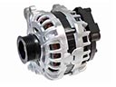 Toyota Sienna Alternator
 Toyota Sienna Starter Solenoid
 Toyota Sienna Alternator Bearing
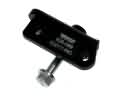 Toyota Sienna Alternator Bracket
 Toyota Sienna Alternator Brush
 Toyota Sienna Alternator Pulley
 Toyota Sienna Armature
 Toyota Sienna Battery Cable
 Toyota Sienna Battery Tray
 Toyota Sienna Car Batteries
 Toyota Sienna Starter Brush
 Toyota Sienna Starter Drive Gear