×
ToyotaParts- Hello
- Login or Register
- Quick Links
- Live Chat
- Track Order
- Parts Availability
- RMA
- Help Center
- Contact Us
- Shop for
- Toyota Parts
- Scion Parts
My Garage
My Account
Cart
OEM Toyota Sienna Alternator
Generator- Select Vehicle by Model
- Select Vehicle by VIN
Select Vehicle by Model
orMake
Model
Year
Select Vehicle by VIN
For the most accurate results, select vehicle by your VIN (Vehicle Identification Number).
6 Alternators found


Toyota Sienna Alternator Part Number: 27060-0P241-84
$290.48 MSRP: $387.48You Save: $97.00 (26%)Ships in 1-3 Business Days
Toyota Sienna Alternator Part Number: 27060-36061
$359.33 MSRP: $526.61You Save: $167.28 (32%)Ships in 1-2 Business Days
Toyota Sienna Alternator Assembly, With Regulator Part Number: 27060-31410
$452.51 MSRP: $663.17You Save: $210.66 (32%)Ships in 1-2 Business Days
Toyota Sienna Alternator Part Number: 27060-20090-84
$246.13 MSRP: $349.27You Save: $103.14 (30%)Ships in 1-3 Business Days
Toyota Sienna Alternator Part Number: 27060-0A110-84
$187.73 MSRP: $249.67You Save: $61.94 (25%)Ships in 1-3 Business Days
Toyota Sienna Alternator Part Number: 27060-0A130-84
$218.95 MSRP: $291.55You Save: $72.60 (25%)Ships in 1-3 Business Days
Toyota Sienna Alternator
Choose genuine Alternator that pass strict quality control tests. You can trust the top quality and lasting durability. Shopping for OEM Alternator for your Toyota Sienna? Our website is your one-stop destination. We stock an extensive selection of genuine Toyota Sienna parts. The price is affordable so you can save more. It only takes minutes to browse and find the exact fit. Easily add to cart and check out fast. Our hassle-free return policy will keep you stress-free. We process orders quickly for swift delivery. Your parts will arrive faster, so you can get back on the road sooner.
Toyota Sienna Alternator Parts and Q&A
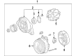
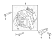
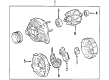
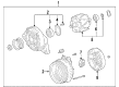
- Q: How to remove the alternator on Toyota Sienna?A:Starting the alternator replacement demands first shutting out the V-bank cover sub-assembly and disconnecting the front wheel RH and the No. 1 engine under cover. The next task requires detachment of the front fender apron seal RH followed by engine coolant drain. The alternator removal procedure starts by taking out the No. 2 air cleaner inlet followed by the battery and then comes the front bumper assembly and front bumper energy absorber. Start by removing the No. 1 air cleaner inlet then disconnect the Radiator reserve tank hose or pipe followed by disconnecting the No. 1 as well as No. 2 radiator hoses. You should remove the hood lock release lever protector along with the hood lock assembly and hood lock support sub-assembly. The cooling fan ECU connector gets disconnected followed by removal of the radiator upper support sub-assembly. After removing the No. 2 oil cooler outlet tube sub-assembly it is necessary to remove the headlight assembly RH, radiator side deflector RH, and headlight bracket RH. The service technician must remove the pressure feed tube assembly together with the radiator support cushion and the No. 1 radiator support and finally extract the radiator assembly that includes the fan shroud with the fan motor. Next, remove the V-ribbed belt. The removal process of the generator assembly begins by disconnecting the terminal cap followed by removing the nut and breaking the wire harness from terminal B then discharging both the generator connector and the compressor and magnetic clutch connector. Detach the two wire harness clamps while removing the two bolts in addition to the block-side bolt. The first step requires disconnecting the wire harness clamp then extracting the generator assembly while also removing the bolt and wire harness clamp stay until the bolt along with bracket separate.
- Q: How to service and repair the alternator on Toyota Sienna?A:The alternator service begins with disassembly where you should first remove the rear end cover by taking out the nut and terminal insulator then the screw followed by the three nuts and plate terminal and end cover. Before proceeding to detach the brush holder along with the voltage regulator you must pop off the brush holder cover followed by removing the 5 screws. You must first remove the rectifier holder by taking out its four screws as well as its four rubber insulators and the seal plate. The pulley holding tool (Special Service Tool 09820-63011) needs combination with a torque wrench to achieve 39 Nm (400 kgf.cm, 29 ft.lbf) clockwise tightening force when securing the tool against the rotor shaft. Position the adapter in a vise before inserting the socket followed by the pulley nut which must be turned counterclockwise only until a half turn while maintaining safety of the rotor shaft. First remove the generator from its adapter before taking off the socket, pulley holding tool and pulley and pulley nut. Move on to disconnect the rectifier end frame by first disconnecting all 4 nuts and cord clip then utilizing Special Service Tool 09286-46011 to separate the rectifier end frame before taking off the generator washer. To reassemble start by fitting the rotor to the drive end frame where you first attach the rectifier end frame onto the pulley followed by the rotor. The generator washer installation begins with placing it onto the rotor before applying a 29 mm socket wrench and press to gently insert the rectifier end frame while securing it with the cord clip and 4 nuts. Torque Nut A to 4.5 N.m (46 kgf.cm, 40 in.lbf) and Nut B to 5.4 N.m (55 kgf.cm, 48 in.lbf). Before tightening the pulley nut, manually install the pulley but finish the installation with a pulley holding tool (Special Service Tool 09820-63011) by torqueing it clockwise to 111 N.m (1,132 kg.cm, 82 ft.lb). Install the seal plate onto the rectifier end frame and then mount the 4 rubber insulators onto each lead wire before fastening the rectifier holder with 4 screws that need 2.9 N.m (30 kgf.cm, 26 in.lbf) torque. Install the 5 screws on the rectifier end frame by selecting correct holder installation direction before torquing them to 2.0 N.m (20 kgf.cm, 18 in.lbf), and complete the installation with the brush holder cover. The final installation task includes attaching the end cover together with plate terminal through 3 nuts and a screw. Torque the screw to 3.9 N.m (39 kgf.cm, 35 in.lbf) and the nut to 4.4 N.m (45 kgf.cm, 39 in.lbf) then install the terminal insulator with the nut and torque to 4.1 N.m (42 kgf.cm, 36 in.lbf). Verify smooth rotor rotation.


Related Toyota Sienna Parts
 Toyota Sienna Car Battery
 Toyota Sienna Battery Terminal
 Toyota Sienna Voltage Regulator
 Toyota Sienna Alternator Bearing
 Toyota Sienna Alternator Bracket
 Toyota Sienna Alternator Brush
 Toyota Sienna Alternator Case Kit
 Toyota Sienna Alternator Pulley
 Toyota Sienna Armature
 Toyota Sienna Battery Cable
 Toyota Sienna Battery Tray
 Toyota Sienna Starter Brush