×
ToyotaParts- Hello
- Login or Register
- Quick Links
- Live Chat
- Track Order
- Parts Availability
- RMA
- Help Center
- Contact Us
- Shop for
- Toyota Parts
- Scion Parts
My Garage
My Account
Cart
OEM Toyota Sienna Radiator
Cooling Radiator- Select Vehicle by Model
- Select Vehicle by VIN
Select Vehicle by Model
orMake
Model
Year
Select Vehicle by VIN
For the most accurate results, select vehicle by your VIN (Vehicle Identification Number).
16 Radiators found


Toyota Sienna Radiator Part Number: 16041-0A380
$347.15 MSRP: $508.75You Save: $161.60 (32%)Ships in 1-3 Business Days
Toyota Sienna Radiator Part Number: 16410-AZ035
$166.98 MSRP: $236.00You Save: $69.02 (30%)Ships in 1-3 Business Days

Toyota Sienna Radiator Part Number: 16041-0P201
$358.08 MSRP: $524.78You Save: $166.70 (32%)Ships in 1-3 Business Days
Toyota Sienna Radiator Part Number: 16041-0A402
$358.74 MSRP: $525.73You Save: $166.99 (32%)Ships in 1-3 Business Days


Toyota Sienna Cooling Module Part Number: 16410-0P161
$640.80 MSRP: $939.09You Save: $298.29 (32%)Ships in 1-3 Business Days


Toyota Sienna Radiator Part Number: 16410-AZ028
$239.86 MSRP: $341.92You Save: $102.06 (30%)Ships in 1-3 Business Days
Toyota Sienna Radiator Part Number: 16041-0P260
$278.27 MSRP: $397.31You Save: $119.04 (30%)Ships in 1-3 Business Days
Toyota Sienna Auxiliary Radiator Part Number: G9010-48100
$436.74 MSRP: $640.04You Save: $203.30 (32%)Ships in 1-3 Business Days
Toyota Sienna Radiator Assembly Part Number: 16400-0P370
$572.88 MSRP: $839.56You Save: $266.68 (32%)Ships in 1-3 Business Days
Toyota Sienna Radiator Assembly Part Number: 16410-AZ021
$117.93 MSRP: $166.69You Save: $48.76 (30%)Ships in 1-3 Business Days
Toyota Sienna Radiator Part Number: 16400-F0120
$273.53 MSRP: $390.54You Save: $117.01 (30%)Ships in 1-3 Business DaysToyota Sienna Radiator Assembly Part Number: 16041-0P280
$292.22 MSRP: $417.22You Save: $125.00 (30%)Ships in 1-3 Business Days
Toyota Sienna Radiator Part Number: 16041-0P270
$295.70 MSRP: $422.19You Save: $126.49 (30%)Ships in 1-3 Business DaysToyota Sienna Radiator Assembly Part Number: 16400-0A072
$340.54 MSRP: $486.22You Save: $145.68 (30%)Ships in 1-3 Business Days


Toyota Sienna Radiator Assembly Part Number: 16400-0A210
Toyota Sienna Radiator Part Number: 16410-YZZAX
Toyota Sienna Radiator
Choose genuine Radiator that pass strict quality control tests. You can trust the top quality and lasting durability. Shopping for OEM Radiator for your Toyota Sienna? Our website is your one-stop destination. We stock an extensive selection of genuine Toyota Sienna parts. The price is affordable so you can save more. It only takes minutes to browse and find the exact fit. Easily add to cart and check out fast. Our hassle-free return policy will keep you stress-free. We process orders quickly for swift delivery. Your parts will arrive faster, so you can get back on the road sooner.
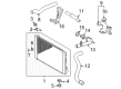
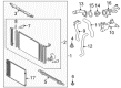
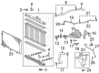
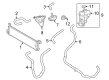
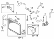
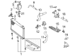
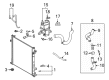
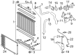
Sienna Radiators are used in the Toyota Sienna to help carry off heat from the coolant that circulates within the automotive engine. Usually constructed from fins and tubes and one or two tanks for inlet and outlet, the radiator is usually fixed in the front part of the car so that it can easily access the airflow. Nevertheless, it is good to know that most of the radiators are of aluminum core and but can also come in copper/brass. There are various forms of performance radiators available that are better than those that come factory fitted, these are lightweight aluminum designs and enhanced design for better cooling. To avoid problems associated with overheating, leaking fluid, and rusty build up, simple practices like outer washing, fluid level control, and flushing should be carried out regularly.
Toyota Sienna Radiator Parts and Q&A
- Q: How to install the radiator on Toyota Sienna?A:When installing the radiator start by attaching the inlet hose to the radiator before tightening the inlet sub-assembly bolt to 7.1 Nm (72 kgf-cm, 63 in-lbf). The first step involves fixing the No. 2 radiator support through 2 bolts which receive 12.7 Nm (130 kgf-cm, 112 in-lbf) torque followed by radial nut inlet hose attachment to the radiator with a securing bolt oriented at 7.1 Nm (72 kgf-cm, 63 in-lbf). Then attach the radiator support lowers. Fasten the radiator to the shroud with the Fan Motor that contains two bolts to apply 6 Nm (61 kgf-cm, 4 ft-lbf) torque. Install the radiator assembly while mounting the fan shroud with fan motor then tighten the condenser assembly with two bolts which need 3.9 Nm (40 kgf-cm, 35 in-lbf) torque. Fasten the No. 1 radiator support to the radiator assembly with 6 bolts according to these values: Bolt A receives 13 Nm (130 kgf-cm, 9 ft-lbf) while Bolt B requires 3.9 Nm (40 kgf-cm, 35 in-lbf) followed by Bolt C needing 6 Nm (61 kgf-cm, 4 ft-lbf). Also attach the clamp. 2 radiator support cushions should be installed on the No. 1 radiator support while the pressure feed tube assembly can be installed using 2 bolts with a torque setting of 7.8 Nm (80 kgf-cm, 69 in-lbf). Mount the radiator side deflector RH by first tightening 3 claws and then installing the headlight bracket RH by using its 3 nuts. The installation procedure for the headlight assembly RH mirrors that of the LH side. The assembled No. 2 oil cooler outlet tube sub-assembly requires installation with 2 bolts receiving 6 Nm (61 kgf-cm, 4 ft-lbf) torque. Next, position No. 1 transmission oil cooler hoses through the radiator before linking both No. 1 oil cooler inlet and outlet hoses to the No. 2 oil cooler outlet tube sub-assembly. The radiator upper support sub-assembly requires 4 bolts torqued to 5.0 Nm (51 kgf-cm, 44 in-lbf) prior to connecting the cooling fan ECU connector with its clamp. The hood lock support sub-assembly receives two bolts for installation and a clamp for attachment before linking the low pitched horn, high pitched horn and ambient temperature sensor connectors. Mount the cable to the hood lock assembly using 3 bolts that should reach 8 Nm (82 kgf-cm, 6 ft-lbf) inside the tight fittings while creating a proper connection with the hood courtesy switch. Complete installation begins with attaching the hood lock release lever protector using the 4 claws before connecting the No. 2 radiator hose then moving forward to the No. 1 radiator hose and finally the radiator reserve tank hose or pipe. The installation process requires the front bumper assembly, No. 1 air cleaner inlet, front bumper energy absorber, and battery and finally the No. 2 air cleaner inlet. The technician should add engine coolant to the system and examine for any coolant leaks while adding automatic transaxle fluid before checking its fluid level. The last task involves installing the No. 1 engine under cover while also installing the V-bank cover sub-assembly along with preparations for performing headlight and fog light aim adjustments which include necessary inspections and adjustments.
- Q: How to remove the radiator on Toyota Sienna?A:Beginning the radiator removal requires workers to detach the V-bank cover sub-assembly and No. 1 engine under cover before draining engine coolant. You need to start by taking out the No. 2 air cleaner inlet and battery and front bumper assembly before proceeding to remove the front bumper energy absorber together with the No. 1 air cleaner inlet. The radiator reserve tank hose or pipe needs removal in addition to disconnecting both No. 1 radiator hose connections and the No. 2 radiator hose. Unfasten the 4 claws holding the hood lock release lever protector then remove the hood lock assembly by disconnecting its connector and detaching three bolts and cable. The hood lock support sub-assembly becomes removable after disconnecting its ambient temperature sensor connector with clamp together with horn connectors. Remove the radiator upper support sub-assembly after detaching both fan ECU connector and clamp and then removing 4 bolts. The removal of the No. 2 oil cooler outlet tube sub-assembly begins by removing both No. 1 oil cooler inlet and outlet hoses and No. 1 transmission oil cooler hoses and then unfastening the 2 bolts. Disengage three claws from both the right headlight assembly and RH radiator side deflector to remove them before taking off the right headlight bracket with its three nuts. Two bolts installed into the pressure feed tube assembly allow removal of the tube while the No. 1 radiator support's two support cushions should also be removed. Sever the clamp before removing the six bolts from the No. 1 radiator support. The last step requires separating the condenser assembly from the radiator assembly with fan shroud while also removing the Fan Motor and radiator support lowers along with the No. 2 radiator support through its 2 bolts. The radiator accepts the inlet sub-assembly removal by disconnecting the inlet hose followed by unscrewing the bolt.


Related Toyota Sienna Parts
 Toyota Sienna Thermostat
 Toyota Sienna Coolant Reservoir
 Toyota Sienna Radiator Cap
 Toyota Sienna Coolant Reservoir Hose
 Toyota Sienna Fan Blade
 Toyota Sienna Fan Motor
 Toyota Sienna Fan Shroud
 Toyota Sienna Radiator Hose
 Toyota Sienna Thermostat Gasket
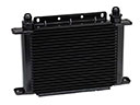 Toyota Sienna Transmission Oil Cooler
 Toyota Sienna Water Pump Gasket
 Toyota Sienna Water Pump Pulley