×
ToyotaParts- Hello
- Login or Register
- Quick Links
- Live Chat
- Track Order
- Parts Availability
- RMA
- Help Center
- Contact Us
- Shop for
- Toyota Parts
- Scion Parts
My Garage
My Account
Cart
OEM 2007 Toyota Sienna Alternator
Generator- Select Vehicle by Model
- Select Vehicle by VIN
Select Vehicle by Model
orMake
Model
Year
Select Vehicle by VIN
For the most accurate results, select vehicle by your VIN (Vehicle Identification Number).
1 Alternator found


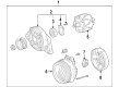
2007 Toyota Sienna Alternator
Part Number: 27060-0P241-84$290.48 MSRP: $387.48You Save: $97.00 (26%)Ships in 1-3 Business DaysProduct Specifications- Other Name: Reman Alternator; Pulley
- Replaces: 27060-0P240, 27060-0P241
- Item Weight: 3.00 Pounds
- Item Dimensions: 9.7 x 8.2 x 7.4 inches
- Condition: New
- SKU: 27060-0P241-84
- Warranty: This genuine part is guaranteed by Toyota's factory warranty.
2007 Toyota Sienna Alternator
Looking for affordable OEM 2007 Toyota Sienna Alternator? Explore our comprehensive catalogue of genuine 2007 Toyota Sienna Alternator. All our parts are covered by the manufacturer's warranty. Plus, our straightforward return policy and speedy delivery service ensure an unparalleled shopping experience. We look forward to your visit!
2007 Toyota Sienna Alternator Parts Q&A
- Q: How to remove and install the alternator and prepare for headlight and fog light aim adjustment on 2007 Toyota Sienna?A: The process to uninstall the alternator starts with removing the V-bank cover sub-assembly together with front wheel RH and front fender apron seal RH, plus No.1 engine under cover and drain engine coolant. Start by removing No.2 air cleaner inlet followed by the battery then front bumper assembly and front bumper energy absorber before taking out No.1 air cleaner inlet and disconnecting the radiator reserve tank hose or pipe alongside No.1 radiator hose and No.2 radiator hose. The alternator replacement process requires the removal of the hood lock release lever protector with the hood lock assembly and hood lock support sub-assembly. This sequence proceeds with disconnecting the cooling fan ECU connector before taking out the radiator upper support sub-assembly and disconnecting the No.2 oil cooler outlet tube sub-assembly. Progress into disassembly by removing the following components: headlight assembly RH, radiator side deflector RH and headlight bracket RH, as well as pressure feed tube assembly, radiator support cushion, No.1 radiator support and radiator assembly with fan shroud and fan motor. The V-ribbed belt and generator assembly are removed through proper sequence starting with removal of the terminal cap followed by nut removal then disconnecting terminal B wire harness before disconnecting the generator connector and disconnecting the connector from the compressor and magnetic clutch. From here follow steps for removing the two wire harness clamps while removing the two bolts and the bolt from the cylinder block. The process ends with removing the generator assembly combined with the bolt and wire harness clamp stay and bolt along with bracket. The first step of installation includes bracket-fastening the generator assembly with a bolt while maintaining a Torque of 20 N.m after which install the wire harness clamp stay at 8.4 N.m Torque followed by wire harness clamp attachment. The generator assembly requires installation on the cylinder block through the bolt (Torque: 20 N.m) followed by installation of the two bolts (Torque: 43 N.m). Connect the generator connector then fit the generator wire with its nut (Torque: 9.8 N.m) and review the terminal cap. Attach both wire harness clamps together with the magnetic clutch connector to its respective locations on the compressor and magnetic clutch. The installation process involves adding the V-ribbed belt followed by the radiator assembly with fan shroud and fan motor then the No.1 radiator support and its corresponding radiator support cushion together with the pressure feed tube assembly and headlight bracket RH and radiator side deflector RH and headlight assembly RH. The service technician must first connect the No.2 oil cooler outlet tube sub-assembly followed by installing the radiator upper support sub-assembly before reconnecting the cooling fan ECU connector alongside installing the hood lock support sub-assembly, hood lock assembly and hood lock release lever protector. Install the front bumper energy absorber followed by the front bumper assembly then the battery before finalizing with the No.2 air cleaner inlet. At the same time connect the No.2 radiator hose, No.1 radiator hose, and radiator reserve tank hose or pipe. The procedure includes adding engine coolant followed by leak inspection of the coolant system and automatic transaxle fluid installation before checking automatic transaxle fluid level. Front fender apron seal RH and No.1 engine under cover are installed together with the front wheel RH (Torque: 103 N.m) before the V-bank cover sub-assembly is reinstalled. Start by preparing the headlight adjustment of the vehicle and its aiming equipment then move forward with the aim examination and modification of headlights. The technician should set up the vehicle for fog light aim adjustment by performing screen preparation and inspecting and adjusting the fog lights.
Related 2007 Toyota Sienna Parts
 2007 Toyota Sienna Battery Terminal
 2007 Toyota Sienna Starter Solenoid
 2007 Toyota Sienna Alternator Bearing
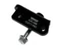 2007 Toyota Sienna Alternator Bracket
 2007 Toyota Sienna Alternator Brush
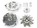 2007 Toyota Sienna Alternator Case Kit
 2007 Toyota Sienna Alternator Pulley
 2007 Toyota Sienna Armature
 2007 Toyota Sienna Battery Tray
 2007 Toyota Sienna Car Batteries
 2007 Toyota Sienna Starter Drive Gear
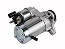 2007 Toyota Sienna Starter Motor