×
ToyotaParts- Hello
- Login or Register
- Quick Links
- Live Chat
- Track Order
- Parts Availability
- RMA
- Help Center
- Contact Us
- Shop for
- Toyota Parts
- Scion Parts
My Garage
My Account
Cart
OEM Scion Brake Master Cylinder
- Select Vehicle by Model
- Select Vehicle by VIN
Select Vehicle by Model
orMake
Model
Year
Select Vehicle by VIN
For the most accurate results, select vehicle by your VIN (Vehicle Identification Number).
16 Brake Master Cylinders found


Scion Master Cylinder Part Number: 47201-21080
$192.91 MSRP: $275.44You Save: $82.53 (30%)Ships in 1-3 Business DaysProduct Specifications- Other Name: Cylinder Sub-Assembly, Brake Stroke Simulator; Brake Master Cylinder; Brake Reservoir; Cylinder Sub-Assembly, Brake Master

Scion Master Cylinder Part Number: 47207-52011
$179.86 MSRP: $256.81You Save: $76.95 (30%)Ships in 1-3 Business DaysProduct Specifications- Other Name: Cylinder Sub-Assembly, Brake Stroke Simulator; Brake Master Cylinder; Brake Reservoir; Cylinder Sub-Assembly, Brake Master Less Reservoir Tank
- Manufacturer Note: W(ABS)

Scion Master Cylinder Part Number: 47201-09800
$183.59 MSRP: $262.13You Save: $78.54 (30%)Ships in 1-3 Business DaysProduct Specifications- Other Name: Cylinder Sub-Assembly, Brake Stroke Simulator; Brake Master Cylinder; Brake Reservoir; Cylinder Sub-Assembly, Brake Master

Scion Master Cylinder Part Number: 47201-74031
$184.87 MSRP: $263.96You Save: $79.09 (30%)Ships in 1-3 Business DaysProduct Specifications- Other Name: Cylinder Sub-Assembly, Brake Stroke Simulator; Brake Master Cylinder; Brake Reservoir; Cylinder Sub-Assembly, Brake Master

Scion Master Cylinder Part Number: 47201-52732
$196.29 MSRP: $280.26You Save: $83.97 (30%)Ships in 1-3 Business DaysProduct Specifications- Other Name: Cylinder Sub-Assembly, Brake Stroke Simulator; Brake Master Cylinder; Brake Reservoir; Cylinder Sub-Assembly, Brake Master
- Replaces: 47201-52730

Scion Master Cylinder Part Number: 47201-21092
$206.19 MSRP: $294.40You Save: $88.21 (30%)Ships in 1-3 Business DaysProduct Specifications- Other Name: Cylinder Sub-Assembly, Brake Stroke Simulator; Brake Master Cylinder; Brake Reservoir; Cylinder Sub-Assembly, Brake Master
- Replaces: 47201-21090

Scion Master Cylinder Part Number: 47201-12A22
$206.19 MSRP: $294.40You Save: $88.21 (30%)Ships in 1-3 Business DaysProduct Specifications- Other Name: Cylinder Sub-Assembly, Brake Stroke Simulator; Brake Master Cylinder; Brake Reservoir; Cylinder Sub-Assembly, Brake Master
- Replaces: 47201-12A20

Scion Master Cylinder Part Number: 47201-WB003
$209.02 MSRP: $298.44You Save: $89.42 (30%)Product Specifications- Other Name: Cylinder Sub-Assembly, Brake Stroke Simulator; Brake Master Cylinder; Brake Reservoir; Cylinder Sub-Assembly, Brake Master
Scion Master Cylinder Part Number: 47201-WB001
$209.02 MSRP: $298.44You Save: $89.42 (30%)Ships in 1-3 Business DaysProduct Specifications- Other Name: Cylinder Sub-Assembly, Brake Stroke Simulator; Brake Master Cylinder; Brake Reservoir; Cylinder Sub-Assembly, Brake Master
Scion Master Cylinder Part Number: 47207-52012
$229.14 MSRP: $327.17You Save: $98.03 (30%)Ships in 1-3 Business DaysProduct Specifications- Other Name: Cylinder Sub-Assembly, Brake Stroke Simulator; Brake Master Cylinder; Brake Reservoir; Cylinder Sub-Assembly, Brake Master Less Reservoir Tank
- Manufacturer Note: W(ABS)
Scion Master Cylinder Part Number: 47207-52040
$280.10 MSRP: $399.93You Save: $119.83 (30%)Ships in 1-3 Business DaysProduct Specifications- Other Name: Cylinder Sub-Assembly, Brake Stroke Simulator; Brake Master Cylinder; Brake Reservoir; Cylinder Sub-Assembly, Brake Master Less Reservoir Tank
Scion Master Cylinder Part Number: 47201-52432
$291.35 MSRP: $415.99You Save: $124.64 (30%)Ships in 1-3 Business DaysProduct Specifications- Other Name: Cylinder Sub-Assembly, Brake Stroke Simulator; Brake Master Cylinder; Brake Reservoir
- Replaces: 47201-52430

Scion Master Cylinder Part Number: 47207-52041
$296.60 MSRP: $423.47You Save: $126.87 (30%)Ships in 1-3 Business DaysProduct Specifications- Other Name: Cylinder Sub-Assembly, Brake Stroke Simulator; Brake Master Cylinder; Brake Reservoir; Cylinder Sub-Assembly, Brake Master Less Reservoir Tank

Scion Master Cylinder, Driver Side Part Number: SU003-10514
$322.91 MSRP: $461.05You Save: $138.14 (30%)Ships in 1-3 Business DaysProduct Specifications- Other Name: Magazine Cylinder Assembly Left-Hand; Brake Master Cylinder; Brake Reservoir; Cylinder Sub-Assembly, Brake Master
- Position: Driver Side
- Replaces: SU003-04242
Scion Master Cylinder Part Number: 47201-52422
Product Specifications- Other Name: Cylinder Sub-Assembly, Brake Stroke Simulator; Brake Master Cylinder; Brake Reservoir
- Replaces: 47201-52420
Scion Master Cylinder Part Number: 47201-52742
$209.80 MSRP: $299.55You Save: $89.75 (30%)Product Specifications- Other Name: Cylinder Sub-Assembly, Brake Stroke Simulator; Brake Master Cylinder; Brake Reservoir; Cylinder Sub-Assembly, Brake Master
- Replaces: 47201-52740, 47201-52741
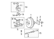
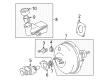
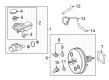
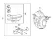
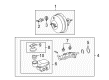
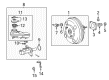
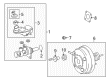
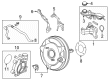
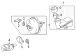
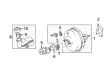
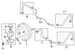
Scion Brake Master Cylinder
OEM parts deliver unmatched quality you can rely on. They pass extensive quality control inspections. Scion produces them to the official factory specifications. This process helps prevent defects and imperfections. So you can get exceptional lifespan and a flawless fit. Need new OEM Scion Brake Master Cylinder? You'll love our wide selection of genuine options. Shop in minutes and skip the hunt. Our prices are unbeatable, you'll save time and money. It's easy to shop and find the right piece. Our committed customer service team gives professional help from start to finish. Every part includes a manufacturer's warranty. We ship quickly, your parts will arrive fast at your door.
Scion Brake Master Cylinder translates the force of the pedals into sure hydraulic power to provide assurance in stopping. The brand attracted youthful drivers by foregoing haggle, bold paint options, and allowing purchasers to combine audio components and body parts to transform their rides into a personalized and affordable move. Scion was also Toyota's playground of ideas, as it dumped the limited Release Series production and digital worlds such as Scion City, and discovered that risk and experimentation can sell more than a million cars in thirteen years alone. Scion is persuading first-time owners to jump into the brand with transparent prices and small, fuel-efficient footprints, keeping wallets relaxed as downtown parking and commute to campus became painless. Scion might have gone out of business in 2016, but its spirit of customization and no-nonsense buying lives on via many Toyota dealerships as they serve as a reminder to customers that cars can be fun before they are functional. The Brake Master Cylinder contains two pistons in two hydraulic systems such that when one side goes dead, the other maintains the fluid flow to ensure that the pedal remains solid and the car remains in control even in times of unforeseen stops. Brake Master Cylinder integrates the power of cast aluminum with architecturally tight reservoirs, thus making the fluid remain clean, reducing weight, and ending corrosion before it even begins. Brake Master Cylinder presses that protected fluid through lines immediately, one-to-one translation of toe force to clamp force which does not fade, giving each model the same crisp, repeatable strike on the rotors. Brake Master Cylinder requires regular fluid inspection since contaminated fluid decreases reaction and robs stopping distance.
Scion Brake Master Cylinder Parts and Q&A
- Q: How to reassemble the brake master cylinder on Scion tC?A:The brake master cylinder assembly begins with checking for interior scratches before obtaining a replacement if needed. The vise must hold the master cylinder in place through aluminum plates before the vise mechanism activates. After applying lithium soap base glycol grease to rubber components place the No. 1 and No. 2 pistons inside the master cylinder body with straight alignment to prevent damage. The piston must be pushed then the new gasket and piston stopper bolt should be installed before torquing the bolt to 10 Nm (102 kgf-cm, 7 ft-lbf). Using snap ring pliers correctly install the hole snap ring and protect the cylinder body from scratches before applying new lubrication and O-ring installation to the master cylinder body. When installing the master cylinder union with stopper screw you must first apply lithium soap base glycol grease and silicon grease to the two grommets before mounting them on the master cylinder body. Check and regulate brake booster push rod position using Special Service Tool: 09737-00013 which produces contact between the piston when lowering the rod. The service tool designated as Special Service Tool: 09737-00012 can serve as an alternative option for this task. Measure the brake booster push rod clearance by setting tool with the flat tip dipped in chalk in an inverted position between the rod and tool rim. The tool clearance should be precisely 0 mm (0 in.). The clear space between push rod and special service tool represents a need for more push rod extension but an inadequate push rod extension reveals insufficient protrusion. The push rod length should be adjusted according to need while the rod is grabbed with Special Service Tool: 09737-00020 using a 7 mm socket driver to check push rod clearance once more after adjustment.
- Q: How to install the brake master cylinder on Scion xB?A:The brake master cylinder installation starts with push rod check and adjustment of the brake booster under no vacuum conditions through brake pedal repetitive depressions with the engine off. The new brake master cylinder accessory tool should have chalk placed on its tip before being set on the brake booster assembly to measure the push rod clearance against the accessory tool which must measure 0 mm (0 in.). If the specified clearance between push rod and accessory tool is not attained then adjust the push rod length with Special Service Tool: 09737-00020 and a socket driver sized for 7 mm (0.28 in.) You should install a new O-ring on the brake master cylinder sub-assembly before installing the sub-assembly together with its wire harness clamp bracket using 2 nuts that require 13 Nm (127 kgf-cm, 9 ft-lbf) torque. The installation of 2 brake tubes onto the brake master cylinder sub-assembly should use a union nut wrench with parallel alignment and torque to 15 Nm (155 kgf-cm, 11 ft-lbf) without the wrench or 14 Nm (143 kgf-cm, 10 ft-lbf) when the wrench is present. Place the harness clamp on the wire harness clamp bracket then mount the wire harness onto the brake master cylinder sub-assembly before making the brake fluid level warning switch connector connection. Connect the tubular reservoir of the clutch system through its clip for manual transaxle models. Fasten all components starting with the air cleaner assembly followed by the outer cowl top panel, front wiper motor with its link, the cowl top ventilator louvers for left and right halves, the hood to cowl top seal, both front wiper arm and blade assemblies and the windshield wiper arm cover. The brake fluid reservoir needs to be filled with the correct fluid before bleeding the master cylinder combined with brake lines and actuator and checking the reservoir fluid level while inspecting for brake fluid leakages.