×
ToyotaParts- Hello
- Login or Register
- Quick Links
- Live Chat
- Track Order
- Parts Availability
- RMA
- Help Center
- Contact Us
- Shop for
- Toyota Parts
- Scion Parts
My Garage
My Account
Cart
OEM Scion Wheel Hub
Wheel Axle Hub- Select Vehicle by Model
- Select Vehicle by VIN
Select Vehicle by Model
orMake
Model
Year
Select Vehicle by VIN
For the most accurate results, select vehicle by your VIN (Vehicle Identification Number).
16 Wheel Hubs found


Scion Hub Assembly Part Number: 43550-0R020
$283.78 MSRP: $405.18You Save: $121.40 (30%)Ships in 1-3 Business DaysProduct Specifications- Other Name: Hub&Bearing Assembly; Front Wheel Bearing & Hub; Wheel Hub Repair Kit; Axle Bearing; Front Hub & Bearing; Hub Sub-Assembly for Front Axle, Passenger & Driver Side; Wheel Bearing Assembly.
- Replaces: 43550-42020


Scion Hub Assembly, Front Part Number: SU003-00782
$132.92 MSRP: $175.00You Save: $42.08 (25%)Ships in 1-3 Business DaysProduct Specifications- Other Name: Hub Unit Complete Front; Wheel Bearing & Hub Assembly; Wheel Hub Repair Kit; Axle Bearing; Front Hub & Bearing; Hub Sub-Assembly, Front Axle, Passenger & Driver Side; Wheel Bearing Assembly.
- Position: Front


Scion Hub Assembly Part Number: 43550-0R010
$327.82 MSRP: $468.06You Save: $140.24 (30%)Ships in 1-2 Business DaysProduct Specifications- Other Name: Hub&Bearing Assembly; Front Wheel Bearing & Hub; Wheel Hub Repair Kit; Axle Bearing; Front Hub & Bearing; Hub Sub-Assembly, Front Axle, Passenger & Driver Side; Wheel Bearing Assembly.
- Replaces: 43550-42010


Scion Wheel Hub, Front Part Number: 43502-52030
$126.07 MSRP: $178.46You Save: $52.39 (30%)Ships in 1-2 Business DaysProduct Specifications- Other Name: Hub Sub-Assembly, Front Axle; Wheel Hub, Front; Wheel Hub Repair Kit; Front Hub; Hub; Hub Sub-Assembly, Front Axle, Passenger Side; Hub Sub-Assembly, Front Axle, Driver Side
- Position: Front


Scion Front Hub Part Number: 43502-52010
$129.94 MSRP: $183.95You Save: $54.01 (30%)Ships in 1-2 Business DaysProduct Specifications- Other Name: Hub Sub-Assembly, Front Axle; Wheel Hub, Front; Wheel Hub Repair Kit; Hub Repair Kit; Hub; Hub Sub-Assembly, Front Axle, Passenger Side; Hub Sub-Assembly, Front Axle, Driver Side; Wheel Hub
- Position: Front


Scion Hub & Bearing, Rear Part Number: 42450-0R010
$430.15 MSRP: $630.40You Save: $200.25 (32%)Ships in 1-3 Business DaysProduct Specifications- Other Name: Hub&Bearing Assembly, Rear Axle; Wheel Bearing & Hub Assembly; Wheel Hub Repair Kit; Axle Bearing; Hub & Bearing Assembly, Rear Axle, Passenger Side; Driver Side; Wheel Bearing & Hub Assembly.
- Position: Rear
- Replaces: 42450-42040


Scion Hub & Bearing, Rear Part Number: 42450-12090
$344.80 MSRP: $505.32You Save: $160.52 (32%)Ships in 1-3 Business DaysProduct Specifications- Other Name: Hub&Bearing Assembly, Rear Axle; Wheel Bearing & Hub Assembly; Wheel Hub Repair Kit; Axle Bearing.; Hub & Bearing Assembly; Rear Axle, Passenger & Driver Side; Wheel Bearing and Hub Assembly.
- Position: Rear


Scion Hub Assembly, Rear Part Number: 42450-52021
$405.41 MSRP: $594.13You Save: $188.72 (32%)Ships in 1-3 Business DaysProduct Specifications- Other Name: Hub&Bearing Assembly, Rear Axle; Wheel Bearing & Hub Assembly; Wheel Hub Repair Kit; Axle Bearing.; Hub & Bearing Assembly, Rear Axle, Passenger & Driver Side; Wheel Bearing and Hub Assembly.
- Manufacturer Note: W(ABS)
- Position: Rear
- Replaces: 42450-52020


Scion Front Hub Part Number: 43502-21010
$122.19 MSRP: $172.97You Save: $50.78 (30%)Ships in 1-3 Business DaysProduct Specifications- Other Name: Hub Sub-Assembly, Front Axle; Wheel Hub, Front; Wheel Hub Repair Kit; Hub; Hub Sub-Assembly, Front Axle, Passenger Side; Hub Sub-Assembly, Front Axle, Driver Side; Wheel Hub
- Position: Front


Scion Front Hub Part Number: 43502-52040
$135.23 MSRP: $191.44You Save: $56.21 (30%)Ships in 1-3 Business DaysProduct Specifications- Other Name: Hub Sub-Assembly, Front Axle; Wheel Hub, Front; Wheel Hub Repair Kit; Hub; Hub Sub-Assembly, Front Axle, Passenger Side; Hub Sub-Assembly, Front Axle, Driver Side; Wheel Hub
- Position: Front


Scion Hub Assembly, Front Part Number: 43502-WB004
$208.90 MSRP: $298.26You Save: $89.36 (30%)Ships in 1-3 Business DaysProduct Specifications- Other Name: Hub Sub-Assembly, Front Axle; Wheel Bearing and Hub Assembly; Wheel Hub Repair Kit; Axle Bearing; Front Hub & Bearing
- Position: Front
- Replaces: 43502-WB002, 43502-WB003, 43502-WB001


Scion Hub Assembly Part Number: 42410-WB002
$115.18 MSRP: $161.67You Save: $46.49 (29%)Ships in 1-2 Business DaysProduct Specifications- Other Name: Hub&Bearing Assembly; Wheel Bearing and Hub Assembly, Rear; Wheel Hub Repair Kit; Wheel Hub Assembly; Wheel Hub; Rear Hub & Bearing; Hub & Bearing Assembly, Rear Axle, Passenger & Driver Side; Wheel Bearing Assembly.
- Replaces: 42410-WB001


Scion Hub & Bearing, Rear Part Number: 42450-52080
$348.32 MSRP: $510.47You Save: $162.15 (32%)Ships in 1-3 Business DaysProduct Specifications- Other Name: Hub&Bearing Assembly, Rear Axle; Wheel Bearing & Hub Assembly, Rear Left/Right; Wheel Hub Repair Kit; Hub & Bearing Assembly; Rear Axle, Passenger & Driver Side; Wheel Bearing and Hub Assembly.
- Position: Rear

Scion Hub Assembly, Rear Part Number: SU003-11362
$255.37 MSRP: $364.61You Save: $109.24 (30%)Ships in 1-2 Business DaysProduct Specifications- Other Name: Hub Unit Complete Rear; Rear Hub & Bearing; Hub & Bearing Assembly, Rear Axle, Passenger Side; Hub & Bearing Assembly, Rear Axle, Driver Side
- Position: Rear
- Replaces: SU003-07348, SU003-00791

Scion Hub & Bearing, Rear Part Number: 42450-74010
$382.94 MSRP: $561.20You Save: $178.26 (32%)Ships in 1-3 Business DaysProduct Specifications- Other Name: Hub&Bearing Assembly, Rear Axle; Wheel Hub Repair Kit; Wheel Bearing Kit; Axle Bearing; Hub & Bearing Assembly; Rear Axle, Passenger & Driver Side; Wheel Bearing and Hub Assembly.
- Position: Rear

Scion Hub Assembly, Rear Part Number: 42450-63011
$487.81 MSRP: $714.89You Save: $227.08 (32%)Ships in 1-3 Business DaysProduct Specifications- Other Name: Hub&Bearing Assembly, Rear Axle; Wheel Bearing & Hub Assembly; Wheel Hub Repair Kit; Axle Bearing; Hub & Bearing Assembly, Rear Axle, Passenger & Driver Side; Wheel Bearing and Hub Assembly.
- Manufacturer Note: W(ABS)
- Position: Rear
- Replaces: 42450-32040, 42450-32041
Scion Wheel Hub
OEM parts deliver unmatched quality you can rely on. They pass extensive quality control inspections. Scion produces them to the official factory specifications. This process helps prevent defects and imperfections. So you can get exceptional lifespan and a flawless fit. Need new OEM Scion Wheel Hub? You'll love our wide selection of genuine options. Shop in minutes and skip the hunt. Our prices are unbeatable, you'll save time and money. It's easy to shop and find the right piece. Our committed customer service team gives professional help from start to finish. Every part includes a manufacturer's warranty. We ship quickly, your parts will arrive fast at your door.
Scion Wheel Hub attaches every wheel to the axle and ensures it rotates smoothly and in line with each drive. The brand shot into the streets of America in 2003 with the simple idea of one-price sales with extreme paint and factory customizations that allowed first-time customers to select the ride that reflected their playlists and sneaker collections. The newcomers were lured into the Scion world via virtual Scion City, guerrilla concerts, ripping off the soul of boring showroom atmosphere and transforming car launching into mixtape releases and street-art microsites. Scion was a live sandbox at Toyota, with experiments of bold body components, smartphone interconnection, and limited Release Series versions, which sold immediately and went on to influence mainstream sedans and crossovers. Scion retired in 2016, although its attitude of individuality, immediate purchase, and price per mile continues to resonate in existing compact vehicles and those who never found a stock bumper they found attractive. The bearings, splined teeth, and mounting flange that fit the wheel to the axle shaft conduct engine torque and fix steering inputs, translating to a smooth, vibration-free movement, and are installed in Wheel Hubs. The brake rotor is also held in position by Wheel Hub, and therefore the calipers clamp evenly and the stopping distances remain consistent in run after run. Wheel Hub comes ready to bolt, with no press work, shaving hours off driveway work and with factory torque specs online. Wheel Hub has to carry loads day by day, shaking off potholes with hardened steel races and seals that keep out grime caused by the rolling elements.
Scion Wheel Hub Parts and Q&A
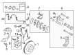
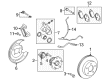
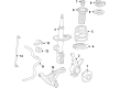
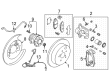
- Q: How to service and repair the front Wheel Hub components on Scion tC?A:A proper inspection of front axle hub bearing starts with these steps: remove the front wheel and disconnect the front disc brake caliper before removing the front disc. The backlash measurement from the axle hub needs a dial indicator to verify that the value stays below 0.05 mm (0.0020 inch). Breach of this limit requires the replacement of the bearing. Check whether the axle hub deviation reaches its maximum value with this tool during the inspection process and exchange the bearing if this limit is exceeded. For removal start by taking out the front wheel and then disconnect the front stabilizer link assembly after unthreading the nut from it before using a hexagon 6 mm wrench to clamp the stud only when the ball joint moves. Using SST 09930-00010 unfasten the front axle hub nut then remove it after applying vehicle brakes. Detach the front speed sensor by pulling off its bolt and removing it from the steering knuckle without causing any damage to the equipment. The front disc brake cylinder assembly can be removed after detaching the 2 bolts and suspending the caliper with a string. Check that oil and grease cannot be found on the friction surfaces before disc removal. Use SST 09628-00011 to disconnect the steering knuckle while removing its tie rod end sub-assembly using a nut along with the needed cotter pin. Remove the front No. 1 suspension lower arm sub-assembly by unfastening its bolt and 2 nuts. You should disconnect the drive shaft using a plastic-faced hammer to prevent boot and speed sensor rotor damage and afterward remove the steering knuckle. SST 09628-62011 allows the removal of front lower ball joint assembly before proceeding to pull out the front axle hub hole snap ring utilizing snap ring pliers. The technician places the steering knuckle into a soft vise and utilizes SST 09520-00031 to extract the axle hub after which they install SST 09950-40011 and multiple variants to extract the bearing inner race. Detach 3 bolts from the front disc brake dust cover before removal. To install the new axle hub bearing into the steering knuckle users should apply SST 09950-60020 and 09950-70010 tools. Press in the axle hub sub-assembly using SST 09608-32010 and 09950-60010 after installing the front disc brake dust cover with 3 bolts which need torquing to 8.3 Nm (85 kgf-cm, 73 inch lbs.). The hole snap ring installation requires snap ring pliers and completion requires attaching the lower ball joint followed by tightening the nut to 103 Nm (1,050 kgf-cm, 76 ft. lbs.) while adding a new cotter pin. The front axle assembly installation requires bolting the drive shaft to the steering knuckle using 2 bolts with 2 nuts which should be tightened to 240 Nm (2,447 kgf-cm, 177 ft. lbs.) while applying engine oil to screw parts if reusing bolts and nuts. Install the front No. 1 suspension lower arm sub-assembly by attaching the lower ball joint first and torques it to 89 Nm (908 kgf-cm, 66 ft. lbs.) before installing the tie rod end sub-assembly and torquing it to 49 Nm (500 kgf-cm, 36 ft.lbs.). When installing the front stabilizer link assembly thread on the nut then tighten it to 74 Nm (755 kgf-cm, 55 ft. lbs.) but maintain the stud with a 6 mm hexagon wrench if the ball joint starts to turn. The front disc assembly requires installation with the front disc brake cylinder assembly using two bolts that should be torqued to 107 Nm (1,090 kgf-cm, 79 ft. lbs.). Ensure that the friction surfaces remain free of oil or grease. Place the new axle hub nut in position through the use of a 30 mm socket wrench and torque it to 216 Nm (2,200 kgf-cm, 159 ft. lbs.). After torquing, use a chisel along with a hammer to stake the axle hub nut. To complete the installation finish by checking the ABS speed sensor signal while inspecting and adjusting the front wheel alignment before torquing the front wheel to 103 Nm (1,050 kgf-cm, 76 ft. lbs.).
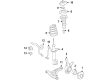
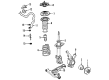
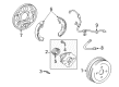
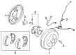
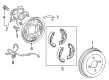
- Q: How to service and repair the front Wheel Hub on Scion xB?A:Service and repair of the front wheel hub starts with wheel removal followed by disc brake cylinder disconnection before removing the front disc. You must check the wheel hub backlash through dial indicator measurement near the hub center which should not exceed 0.05 mm (0.0020 inch). A bearing replacement is necessary when the measurement crosses this threshold. Verify wheel hub deviation with a dial indicator applied to its surface until you find a maximum value of 0.05 mm (0.0020 inch). Replacing the bearing becomes necessary if the measured deviation exceeds this limit.