×
ToyotaParts- Hello
- Login or Register
- Quick Links
- Live Chat
- Track Order
- Parts Availability
- RMA
- Help Center
- Contact Us
- Shop for
- Toyota Parts
- Scion Parts
My Garage
My Account
Cart
OEM Toyota Prius Axle Shaft
Car Axle Shaft- Select Vehicle by Model
- Select Vehicle by VIN
Select Vehicle by Model
orMake
Model
Year
Select Vehicle by VIN
For the most accurate results, select vehicle by your VIN (Vehicle Identification Number).
14 Axle Shafts found


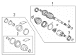
Toyota Prius Axle Assembly, Passenger Side Part Number: 43410-47040
$131.12 MSRP: $185.61You Save: $54.49 (30%)Ships in 1-3 Business Days


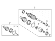
Toyota Prius Axle Assembly, Driver Side Part Number: 43420-47040
$354.11 MSRP: $518.95You Save: $164.84 (32%)Ships in 1 Business Day
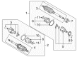
Toyota Prius Axle Assembly, Driver Side Part Number: 43420-47031
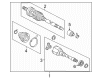
$298.66 MSRP: $452.96You Save: $154.30 (35%)Ships in 1-3 Business DaysToyota Prius Shaft Assembly, Front Drive, Passenger Side Part Number: 43410-47031
$346.72 MSRP: $521.57You Save: $174.85 (34%)Ships in 1-3 Business Days
Toyota Prius Axle Assembly, Driver Side Part Number: 43420-47012
$395.92 MSRP: $580.22You Save: $184.30 (32%)Ships in 1-3 Business Days
Toyota Prius Axle Assembly, Front Driver Side Part Number: 43420-47021
$402.57 MSRP: $589.97You Save: $187.40 (32%)Ships in 1-3 Business DaysToyota Prius Axle Assembly, Front Passenger Side Part Number: 43410-47021
$467.72 MSRP: $685.46You Save: $217.74 (32%)Ships in 1-3 Business Days
Toyota Prius Axle Assembly, Front Driver Side Part Number: 43420-76020
$607.21 MSRP: $889.88You Save: $282.67 (32%)Ships in 1-3 Business DaysToyota Prius Axle Assembly, Front Passenger Side Part Number: 43410-76020
$668.50 MSRP: $979.70You Save: $311.20 (32%)Ships in 1-3 Business Days
Toyota Prius Outer Joint Assembly, Driver Side Part Number: 43470-49597
$238.84 MSRP: $341.01You Save: $102.17 (30%)Ships in 1-3 Business Days
Toyota Prius Outer Joint Assembly, Passenger Side Part Number: 43460-49386
$303.46 MSRP: $433.26You Save: $129.80 (30%)Ships in 1-3 Business Days
Toyota Prius Axle Shaft Assembly, Rear Part Number: 42340-47010
$333.41 MSRP: $476.04You Save: $142.63 (30%)Ships in 1-3 Business Days
Toyota Prius Shaft Assembly, Rear Drive Part Number: 42340-0A030
$325.02 MSRP: $464.06You Save: $139.04 (30%)Ships in 1-2 Business Days
Toyota Prius Axle Assembly, Passenger Side Part Number: 43410-47012
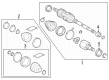
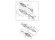
Toyota Prius Axle Shaft
Choose genuine Axle Shaft that pass strict quality control tests. You can trust the top quality and lasting durability. Shopping for OEM Axle Shaft for your Toyota Prius? Our website is your one-stop destination. We stock an extensive selection of genuine Toyota Prius parts. The price is affordable so you can save more. It only takes minutes to browse and find the exact fit. Easily add to cart and check out fast. Our hassle-free return policy will keep you stress-free. We process orders quickly for swift delivery. Your parts will arrive faster, so you can get back on the road sooner.
Toyota Prius Axle Shaft Parts and Q&A
- Q: How to install the axle shaft assembly and related components on the LH and RH sides on Toyota Prius?A:Install the LH front drive shaft assembly by applying ATF to the inboard joint spline before inserting a front drive shaft while facing the snap ring cut area downward with a brass bar and hammer; check installation security by sound or brass bar reaction force and install the front fender apron seal. The RH side calls for the same front drive shaft dust cover installation as previously instructed. To insert the front axle assembly LH while aligning its spline with the front drive shaft, exert barely enough force to the front axle to prevent excessive outward movement while inspecting for foreign matter without harming the oil seal, front drive shaft LH boot or Speed Sensor rotor. The front suspension arm sub-assembly lower LH should be placed downward then fitted with a front lower Ball Joint before tightening the bolt and 2 nuts until achieving 89 Nm (908 kgf-cm, 66 ft-lbf). The steps for installing the front tie rod end sub-assembly LH begin with connecting it to the steering knuckle through the castle nut while following the clip hole realignment process after achieving 60 degrees additional rotation beyond the specified 49 Nm (500 kgf-cm, 36 ft-lbf) torque. A new clip is then installed. Connect the front speed sensor LH to the steering knuckle by installing the wire followed by the flexible hose clamp then applying a bolt torque of 29 Nm (296 kgf-cm, 21 ft-lbf), while keeping the sensor tip undamaged and the wire untwisted. Apply a non-residue solvent to clean threaded drive shaft and axle hub nut parts before tightening a new hub nut with a 30 mm socket wrench to achieve 216 Nm (2,200 kgf-cm, 159 ft-lbf) torque followed by chisel hammer staking of the hub nut. To complete the procedure install the front wheel while applying 103Nm torque (1,050 kgf-cm, 76 ft-lbf). Additionally add the transaxle oil then check the transaxle oil and front wheel alignment alongside testing the ABS speed sensor signal.
- Q: How to remove the axle shaft assembly on Toyota Prius?A:The first step to remove the front drive shaft assembly requires you to drain transaxle oil through using a 10 mm socket hexagon wrench on the drain plug and gasket. Secure the drain plug with a new gasket to a torque of 39 Nm (400 kgf-cm, 29 ft-lbf). Start with the removal of the front wheel and front axle hub nut on the left-hand side using Special Service Tool: 09930-00010 with a hammer to unstake the nut before using a 30 mm socket wrench to extract the nut. Use a hexagon wrench to remove the bolt which allows you to disconnect the Speed Sensor wire alongside the flexible hose from the Shock Absorber. Proceed to remove the bolt together with sensor from steering knuckle while maintaining the sensor free of contamination. The tie rod end sub-assembly LH requires disconnecting from the steering knuckle by removing its clip and castle nut and using Special Service Tool: 09628-00011 while protecting the front disc brake dust cover and Ball Joint dust cover from damage. You must disconnect the No. 1 front suspension arm sub-assembly lower LH by removing its bolt along with two nuts so you can push down the arm to disconnect the front lower ball joint. You must disengage the offside front drive shaft end with a plastic-faced hammer before applying a brass bar and hammer when needed to get the front axle out by pushing it forward. Carefully push the axle with caution because excess force could damage either the outboard joint boot or speed sensor rotor. Subsequently hang the drive shaft down by using a string. The removal of front drive shaft assembly LH requires removing the front fender apron seal followed by usage of Special Service Tool: 09520-01010 to hook out the drive shaft keeping the oil seal and boot free from damage. When removal proves challenging you should hook the tool from a different location. Apply the same methods for removing the front drive shaft assembly RH. The technician should use Special Service Tool: 09608-16042 to support the front axle assembly LH when the vehicle rests on its hub bearing. The inspection of the LH front drive shaft assembly requires examination for looseness in all directions and assessment for damages and boot joint grease leaks while maintaining the drive shaft in a level position.

Related Toyota Prius Parts
 Toyota Prius Wheel Cover
 Toyota Prius Drive Shaft
 Toyota Prius Sway Bar Link
 Toyota Prius Control Arm Bushing
 Toyota Prius Crossmember Bushing
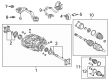
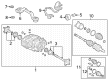
 Toyota Prius Differential
 Toyota Prius Differential Mount
 Toyota Prius Front Cross-Member
 Toyota Prius Strut Housing
 Toyota Prius Strut Mounts
 Toyota Prius Sway Bar Bracket
 Toyota Prius Transfer Case Output Shaft Snap Ring
Browse Toyota Prius Axle Shaft by Years
2025
2024
2023
2022
2021
2020
2019
2018
2017
2016
2015
2014
2013
2012
2011
2010
2009
2008
2007
2006
2005
2004
2003
2002
2001