×
ToyotaParts- Hello
- Login or Register
- Quick Links
- Live Chat
- Track Order
- Parts Availability
- RMA
- Help Center
- Contact Us
- Shop for
- Toyota Parts
- Scion Parts
My Garage
My Account
Cart
OEM 2003 Toyota Prius Axle Shaft
Car Axle Shaft- Select Vehicle by Model
- Select Vehicle by VIN
Select Vehicle by Model
orMake
Model
Year
Select Vehicle by VIN
For the most accurate results, select vehicle by your VIN (Vehicle Identification Number).
2 Axle Shafts found

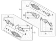
2003 Toyota Prius Axle Assembly, Driver Side
Part Number: 43420-47012$395.92 MSRP: $580.22You Save: $184.30 (32%)Ships in 1-3 Business DaysProduct Specifications- Other Name: Shaft Assembly, Front Drive; CV Axle Assembly, Front Left; GSP Cv Axle; Axle Shaft; Shaft Assembly, Front Drive, Driver Side; CV Axle Assembly
- Position: Driver Side
- Replaces: 43420-47011
- Part Name Code: 43420
- Item Weight: 17.90 Pounds
- Item Dimensions: 30.4 x 5.1 x 5.3 inches
- Condition: New
- Fitment Type: Direct Replacement
- SKU: 43420-47012
- Warranty: This genuine part is guaranteed by Toyota's factory warranty.
 Product Specifications
- Other Name: Shaft Assembly, Front Drive; CV Axle Assembly, Front Right; GSP Cv Axle; Axle Shaft; Shaft Assembly, Front Drive, Passenger Side; CV Axle Assembly
- Position: Passenger Side
- Replaces: 43410-47011
- Part Name Code: 43410
- Item Weight: 22.70 Pounds
- Item Dimensions: 42.8 x 5.4 x 5.5 inches
- Condition: New
- Fitment Type: Direct Replacement
- SKU: 43410-47012
- Warranty: This genuine part is guaranteed by Toyota's factory warranty.
2003 Toyota Prius Axle Shaft
Looking for affordable OEM 2003 Toyota Prius Axle Shaft? Explore our comprehensive catalogue of genuine 2003 Toyota Prius Axle Shaft. All our parts are covered by the manufacturer's warranty. Plus, our straightforward return policy and speedy delivery service ensure an unparalleled shopping experience. We look forward to your visit!
2003 Toyota Prius Axle Shaft Parts Q&A
- Q: How to remove and install the axle shaft on 2003 Toyota Prius?A: The procedure to remove and install the axle shaft begins with supporting the hub bearing using Special Service Tool: 09608-16042 (09608-02021, 09608-02041) to protect it from damage when the weight of the vehicle is applied. When disconnecting the drive shaft from the axle hub you need to exercise caution to safeguard the ABS speed sensor rotor serrations. Start the process by loosening the front wheel nut to 103 Nm then remove both front wheel caps along with the engine under cover before draining the ATF. Use Special Service Tool: 09930-00010 with a hammer to unstake the drive shaft lock nut before removing it under break application conditions with a torque of 216 Nm (2,200 kgf-cm, 159 ft. lbs.). The process requires testing the nut with 49 Nm torque when detaching the tie rod end from the steering knuckle and only tightening the nut more if mismatched holes in a new cotter pin assembly occur before torquing beyond 60 degrees. Remove the tie rod end by applying Special Service Tool: 09628-62011. Disassembly of the lower suspension arm lower ball joint requires removing both nuts and bolt with 142 Nm (1,450 kgf-cm, 105 ft. lbs.) torque specification. The axle hub connection with drive shaft requires a plastic hammer to separate them in a way that avoids boot and ABS speed sensor rotor damage. First isolate the drive shaft using Special Service Tools 09520-01010, 09520-24010 (09520-32040) while ensuring no harm comes to the signature oil seal and dust cover. For the installation process apply gear oil to inboard joint shaft sliding surfaces along with differential case areas followed by inserting the snap ring facing downward before verifying the inboard joint shaft touch point with the pinion shaft. inspect the affected areas to verify that a manual drive shaft removal is impossible and the axial play measures between 2 - 3 mm (0.08 - 0.12 inch). Check the ABS speed sensor signal as well as front wheel alignment at the end of the inspection process.
Related 2003 Toyota Prius Parts
 2003 Toyota Prius Ball Joint
 2003 Toyota Prius Control Arm
 2003 Toyota Prius Lug Nuts
 2003 Toyota Prius Alignment Bolt
 2003 Toyota Prius Bump Stop
 2003 Toyota Prius Coil Spring Insulator
 2003 Toyota Prius Front Cross-Member
 2003 Toyota Prius Shock And Strut Mount
 2003 Toyota Prius Shock and Strut Boot
 2003 Toyota Prius Sway Bar Bracket
 2003 Toyota Prius Sway Bar Bushing
 2003 Toyota Prius Transfer Case Output Shaft Snap Ring