×
ToyotaParts- Hello
- Login or Register
- Quick Links
- Live Chat
- Track Order
- Parts Availability
- RMA
- Help Center
- Contact Us
- Shop for
- Toyota Parts
- Scion Parts
My Garage
My Account
Cart
OEM 2001 Toyota Prius Axle Shaft
Car Axle Shaft- Select Vehicle by Model
- Select Vehicle by VIN
Select Vehicle by Model
orMake
Model
Year
Select Vehicle by VIN
For the most accurate results, select vehicle by your VIN (Vehicle Identification Number).
2 Axle Shafts found

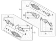
2001 Toyota Prius Axle Assembly, Driver Side
Part Number: 43420-47012$395.92 MSRP: $580.22You Save: $184.30 (32%)Ships in 1-3 Business DaysProduct Specifications- Other Name: Shaft Assembly, Front Drive; CV Axle Assembly, Front Left; GSP Cv Axle; Axle Shaft; Shaft Assembly, Front Drive, Driver Side; CV Axle Assembly
- Position: Driver Side
- Replaces: 43420-47011
- Part Name Code: 43420
- Item Weight: 17.90 Pounds
- Item Dimensions: 30.4 x 5.1 x 5.3 inches
- Condition: New
- Fitment Type: Direct Replacement
- SKU: 43420-47012
- Warranty: This genuine part is guaranteed by Toyota's factory warranty.
 Product Specifications
- Other Name: Shaft Assembly, Front Drive; CV Axle Assembly, Front Right; GSP Cv Axle; Axle Shaft; Shaft Assembly, Front Drive, Passenger Side; CV Axle Assembly
- Position: Passenger Side
- Replaces: 43410-47011
- Part Name Code: 43410
- Item Weight: 22.70 Pounds
- Item Dimensions: 42.8 x 5.4 x 5.5 inches
- Condition: New
- Fitment Type: Direct Replacement
- SKU: 43410-47012
- Warranty: This genuine part is guaranteed by Toyota's factory warranty.
2001 Toyota Prius Axle Shaft
Looking for affordable OEM 2001 Toyota Prius Axle Shaft? Explore our comprehensive catalogue of genuine 2001 Toyota Prius Axle Shaft. All our parts are covered by the manufacturer's warranty. Plus, our straightforward return policy and speedy delivery service ensure an unparalleled shopping experience. We look forward to your visit!
2001 Toyota Prius Axle Shaft Parts Q&A
- Q: How to remove and install the axle shaft on 2001 Toyota Prius?A: Prior to shaft axle removal and installation the hub bearing needs support from Special Service Tool: 09608-16042 (09608-02021, 09608-02041) in case the vehicle weight needs to be rested on it. The complementary set of tasks includes wheel removal with 103 Nm torque followed by engine cover detachment and ATF drainage. Apply brakes when using Special Service Tool: 09930-00010 and a hammer to unstake and remove the drive shaft lock nut until reaching torque of 216 Nm (2,200 kgf-cm, 159 ft. lbs.). When disconnecting the tie rod end from its position on the steering knuckle through nut removal followed by removal of the cotter pin at 49 Nm (500 kgf-cm, 36 ft. lbs.), adjust the nut torque more tightly to reach 60 if hole misalignment occurs when installing the cotter pin. The Special Service Tool: 09628-62011 should be used to disconnect the tie rod end. The lower ball joint needs to be removed from the lower suspension arm through the dismantling of 2 nuts and bolt at 142 Nm torque (1,450 kgf-cm, 105 ft. lbs.). A red plastic hammer should be used to disconnect the drive shaft from the axle hub while safeguarding against boot and ABS speed sensor rotor damage. Use Special Service Tools 09520-01010 and 09520-24010 (09520-32040) to remove the drive shaft with caution applied to the oil seal and dust cover protection. Install gear oil on both the inboard joint shaft and differential case sliding surfaces before properly placing the snap ring orientation down and making sure the inboard joint shaft reaches the pinion shaft. An installed measurement should verify the drive shaft exhibits 2 - 3 mm (0.08 - 0.12 inch) of axial play while preventing manual removal of the shaft. To finish installation you must remove the inboard joint shaft snap ring then finish in the reverse order by checking ABS speed sensor signal and front wheel alignment.
Related 2001 Toyota Prius Parts
 2001 Toyota Prius Ball Joint
 2001 Toyota Prius Control Arm
 2001 Toyota Prius Lug Nuts
 2001 Toyota Prius Alignment Bolt
 2001 Toyota Prius Bump Stop
 2001 Toyota Prius Coil Spring Insulator
 2001 Toyota Prius Front Cross-Member
 2001 Toyota Prius Shock And Strut Mount
 2001 Toyota Prius Shock and Strut Boot
 2001 Toyota Prius Sway Bar Bracket
 2001 Toyota Prius Sway Bar Bushing
 2001 Toyota Prius Transfer Case Output Shaft Snap Ring