×
ToyotaParts- Hello
- Login or Register
- Quick Links
- Live Chat
- Track Order
- Parts Availability
- RMA
- Help Center
- Contact Us
- Shop for
- Toyota Parts
- Scion Parts
My Garage
My Account
Cart
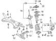
OEM 2001 Toyota Prius Control Arm
Suspension Arm- Select Vehicle by Model
- Select Vehicle by VIN
Select Vehicle by Model
orMake
Model
Year
Select Vehicle by VIN
For the most accurate results, select vehicle by your VIN (Vehicle Identification Number).
2 Control Arms found

 Product Specifications
- Other Name: Arm Sub-Assembly, Suspension; Suspension Control Arm, Front Left; Control Arm Assembly; Arm Sub-Assembly, Front Suspension, Lower Driver Side; Suspension Control Arm; Control Arm
- Position: Lower Driver Side
- Replaces: 48069-47020
- Part Name Code: 48069
- Item Weight: 7.30 Pounds
- Item Dimensions: 20.1 x 4.1 x 19.5 inches
- Condition: New
- Fitment Type: Direct Replacement
- SKU: 48069-47021
- Warranty: This genuine part is guaranteed by Toyota's factory warranty.
2001 Toyota Prius Lower Control Arm, Passenger Side
Part Number: 48068-47021$210.39 MSRP: $300.38You Save: $89.99 (30%)Product Specifications- Other Name: Arm Sub-Assembly, Suspension; Suspension Control Arm, Front Right; Control Arm Assembly; Arm Sub-Assembly, Front Suspension, Lower Passenger Side; Suspension Control Arm; Control Arm
- Position: Passenger Side
- Replaces: 48068-47020
- Part Name Code: 48068
- Item Weight: 7.30 Pounds
- Item Dimensions: 20.1 x 4.0 x 19.8 inches
- Condition: New
- Fitment Type: Direct Replacement
- SKU: 48068-47021
- Warranty: This genuine part is guaranteed by Toyota's factory warranty.
2001 Toyota Prius Control Arm
Looking for affordable OEM 2001 Toyota Prius Control Arm? Explore our comprehensive catalogue of genuine 2001 Toyota Prius Control Arm. All our parts are covered by the manufacturer's warranty. Plus, our straightforward return policy and speedy delivery service ensure an unparalleled shopping experience. We look forward to your visit!
2001 Toyota Prius Control Arm Parts Q&A
- Q: How to remove the control arm on 2001 Toyota Prius?A: The first step to remove the control arm begins with removing the front wheel and using 103 Nm torque. The engine under cover requires removal as the subsequent step. The lower suspension arm requires disconnecting RH and LH tie rod ends which start with unscrewing the cotter pin and nut to 49 Nm (500 kgf-cm, 36 ft. lbs.) followed by using Special Service Tool: 09628-62011 to separate the tie rod end from the steering knuckle before repeating the process for the opposite side. To detach the RH and LH stabilizer bar links use a hexagon (5 mm) wrench for holding the stud when the ball joint rotates with the nut then apply torque of 74 Nm (755 kgf-cm, 55 ft. lbs.) to remove the nut and link from the shock absorber. The process must be repeated for the other side. Disconnection of the lower suspension arms from the lower ball joints requires removing the bolt and 2 nuts while maintaining a torque of 142 Nm (1,450 kgf-cm, 105 ft. lbs.), the procedure should be repeated on the other side. Its essential to first loosen with 137 Nm torque (1,397 kgf-cm and 101 ft. lbs.) the 2 lower suspension arm set bolts while remembering to torque these bolts when stabilizing the suspension during installation. The procedure involves disconnecting the sliding yoke while placing a transmission jack under the suspension member to remove the bolt and nut which allows disconnecting the torque rod from the suspension member with 100 Nm (1,150 kgf-cm, 83 ft. lbs.) torque. The suspension member disconnection from the body requires removal of 4 bolts that need to be tightened to 113 Nm (1,152 kgf-cm, 83 ft. lbs.) on the front side and 157 Nm (1,600 kgf-cm, 116 ft. lbs.) on the rear side. The 2 lower suspension arm set bolts need removal to fully disengage the lower suspension arm from the suspension member. The installation procedure follows the opposite order of removal and the front wheel alignment must be checked after completion.
Related 2001 Toyota Prius Parts
 2001 Toyota Prius Sway Bar Link
 2001 Toyota Prius Alignment Bolt
 2001 Toyota Prius Bump Stop
 2001 Toyota Prius Coil Spring Insulator
 2001 Toyota Prius Coil Springs
 2001 Toyota Prius Control Arm Bolt
 2001 Toyota Prius Front Cross-Member
 2001 Toyota Prius Shock And Strut Mount
 2001 Toyota Prius Shock and Strut Boot
 2001 Toyota Prius Steering Knuckle
 2001 Toyota Prius Strut Housing
 2001 Toyota Prius Sway Bar Bushing