×
ToyotaParts- Hello
- Login or Register
- Quick Links
- Live Chat
- Track Order
- Parts Availability
- RMA
- Help Center
- Contact Us
- Shop for
- Toyota Parts
- Scion Parts
My Garage
My Account
Cart
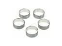
OEM Scion xD Cylinder Head Gasket
Engine Cylinder Head Gasket- Select Vehicle by Model
- Select Vehicle by VIN
Select Vehicle by Model
orMake
Model
Year
Select Vehicle by VIN
For the most accurate results, select vehicle by your VIN (Vehicle Identification Number).
1 Cylinder Head Gasket found

Scion xD Head Gasket Part Number: 11115-37062
$67.41 MSRP: $94.63You Save: $27.22 (29%)Ships in 1-2 Business Days
Scion xD Cylinder Head Gasket
Choose genuine Cylinder Head Gasket that pass strict quality control tests. You can trust the top quality and lasting durability. Shopping for OEM Cylinder Head Gasket for your Scion xD? Our website is your one-stop destination. We stock an extensive selection of genuine Scion xD parts. The price is affordable so you can save more. It only takes minutes to browse and find the exact fit. Easily add to cart and check out fast. Our hassle-free return policy will keep you stress-free. We process orders quickly for swift delivery. Your parts will arrive faster, so you can get back on the road sooner.
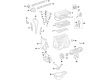
The Scion xD Cylinder Head Gasket is one of those parts that are extensively used in the Scion xD and are quite famous for their efficiency and durability. This important component acts in a way to ensure that combustion gases do not leak and the oil and water do not intermix hence avoiding overheating of the engine and reducing efficiency. The Scion xD models normally come with highly efficient Multi-Layer Steel (MLS) gaskets, which are widely considered to be highly effective and long lasting guaranteeing the finest performance by the Scion xD. Able to fit xD models increases its popularity since everyone wants a car that will not let them down when on the roads. It is recommended that Scion xD Cylinder Head Gasket be checked and replaced frequently to avoid situations that lead to a dangerous climatic compound which may cause a leakage of coolant that leads to overheating of the engine. Some of the signs of a failing gasket includes excessive loss of coolant, and burning smell are some of the reasons why early diagnosis is critical. The features such as the Scion xD's 2ZR-FE DOHC 1.8-liter engine therefore require a high-quality Cylinder Head Gasket to ensure maximum efficiency in the use of fuel. Some of these include anti-lock brakes and traction control; thus, the Scion xD Cylinder Head Gasket is a marvel in the current auto market since it provides and guarantees the driver a great experience and smooth ride regardless of the road conditions.
Scion xD Cylinder Head Gasket Parts and Q&A
- Q: How to install the cylinder head gasket and related components on Scion xD?A:Place a new gasket onto the cylinder block with its Lot No. stamp directed upward while avoiding contact with oil and maintain gasket orientation until the cylinder head installation process. Place a small amount of engine oil on the bolt threads of the 10 cylinder head bolts before tightening each bolt to 49 Nm (500 kgf-cm, 36 ft-lbf) while using a 10 mm bi-hexagon wrench according to the specified order. Apply paint to identify each bolt front section then tighten bolts an extra 90 degree angle and a following 45 degree angle while verifying the paint marks form a 135 degree angle relative to bolt fronts. The valve lash adjuster assembly needs to stay clean then go into engine oil before using Special Service Tool: 09276-75010 to press the check ball in the plunger until air dissipates through up-and-down movements. The lash adjusters should be installed back in their original positions once the plunger exhibits resistance to movement. Maintenance requires engineers to apply engine oil onto the lash adjuster tip and valve stem cap end before installing the No. 1 valve rocker arms. Clean both No. 1 Camshaft bearings then install them while checking that the gap between the cap border and bearing surface measures below 0.7 mm (0.0276 in.). During the same procedure measure 1.05 to 1.75 mm (0.042 to 0.068 inches) for the No. 2 camshaft bearings. The procedure calls for cleaning of the camshaft journals followed by applying engine oil and installing the No. 2 camshaft and main camshaft which is then followed by installing the bearing cap. Check the marks before tightening the 10 bolts to 16 Nm (163 kgf-cm, 12 ft-lbf). Install the camshaft housing sub-assembly by first placing the valve rocker arm properly and afterward applying continuous seal packing followed by a torque of 27 Nm (275 kgf-cm, 20 ft-lbf) on the 17 bolts. Verity that cam lobes face the correct direction before removing any remaining seal packing from the components. Proceed with the installation of the crankshaft timing gear or sprocket, No. 1 chain vibration damper, chain sub-assembly, chain tensioner slipper, No. 2 chain vibration damper, timing chain or belt cover oil seal, timing chain or belt cover sub-assembly, crankshaft pulley, No. 1 chain tensioner assembly, cylinder head cover sub-assembly, Thermostat, water inlet, wire harness clamp bracket, Exhaust Manifold, manifold stay, No. 1 exhaust manifold heat insulator, air tube assembly, No. 1 water by-pass pipe, water inlet hose, water by-pass hose, oil level gage guide, oil level dipstick, fan belt adjusting bar, generator assembly, Fuel Injector, injector vibration insulator, No. 1 delivery pipe spacer, fuel delivery pipe sub-assembly, Intake Manifold, No. 1 Radiator hose, heater water inlet hose A, heater water outlet hose A, No. 2 ventilation hose, radio setting condenser, Ignition Coil assembly, transmission oil filler tube sub-assembly (for Automatic Transaxle), transmission oil level gage sub-assembly (for Automatic Transaxle), No. 1 oil cooler outlet tube (for Automatic Transaxle), No. 1 oil cooler inlet tube (for Automatic Transaxle), No. 2 oil cooler tube clamp (for Automatic Transaxle), front suspension crossmember sub-assembly, engine assembly with transaxle, front axle assembly LH, front axle assembly RH, front lower suspension arm sub-assembly LH, front lower suspension arm sub-assembly RH, front stabilizer link assembly LH, front stabilizer link assembly RH, tie rod end sub-assembly LH, tie rod end sub-assembly RH, Speed Sensor front LH, speed sensor front RH, front Axle Shaft LH nut, front axle shaft RH nut, front Exhaust Pipe assembly, front floor brace center, front console box, rear console box assembly, console box carpet, console box rear cover, console panel upper, shift lever knob sub-assembly (for Manual Transaxle), No. 1 steering column hole cover sub-assembly, steering sliding yoke sub-assembly, column hole cover silencer sheet, clutch release cylinder assembly (for Manual Transaxle), connect fuel tube sub-assembly, connect heater water inlet hose A, connect heater water outlet hose A (from heater unit), connect engine wire, install No. 1 fuel vapor feed hose, install union to check valve hose, install transmission control cable assembly (for Automatic Transaxle), install transmission control cable assembly (for Manual Transaxle), install with pulley compressor assembly, install radiator assembly, install upper radiator support sub-assembly, install upper radiator support absorber, install No. 1 cooler cover, install hood lock assembly, connect No. 1 radiator hose, connect No. 2 oil cooler inlet hose (for Automatic Transaxle), connect No. 1 oil cooler outlet hose (for Automatic Transaxle), install No. 2 radiator hose, install front bumper cover, install fan and generator V belt, adjust fan and generator V belt, inspect fan and generator V belt, install No. 2 cylinder head cover, install battery carrier, install air cleaner bracket, install air cleaner assembly, install outer cowl top panel, install front air shutter seal RH, install front Wiper Motor and link, install cowl top ventilator louver LH, install cowl top ventilator louver sub-assembly, install hood to cowl top seal, install front wiper arm and blade assembly LH, install front wiper arm and blade assembly RH, install front wiper arm head cap, install battery tray, install battery, add engine coolant, add engine oil, inspect for fuel leak, inspect for engine oil leak, inspect for exhaust gas leak, inspect for engine coolant leak, install engine under cover RH, install engine under cover LH, install front wheels, inspect ignition timing, inspect engine idling speed, inspect CO/HC, inspect front wheel alignment, inspect ABS sensor signal (w/ ABS), and inspect VSC sensor signal (w/ VSC).