×
ToyotaParts- Hello
- Login or Register
- Quick Links
- Live Chat
- Track Order
- Parts Availability
- RMA
- Help Center
- Contact Us
- Shop for
- Toyota Parts
- Scion Parts
My Garage
My Account
Cart
OEM 2008 Scion xD Cylinder Head Gasket
Engine Cylinder Head Gasket- Select Vehicle by Model
- Select Vehicle by VIN
Select Vehicle by Model
orMake
Model
Year
Select Vehicle by VIN
For the most accurate results, select vehicle by your VIN (Vehicle Identification Number).
1 Cylinder Head Gasket found

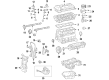
2008 Scion xD Head Gasket
Part Number: 11115-37062$67.41 MSRP: $94.63You Save: $27.22 (29%)Ships in 1-2 Business DaysProduct Specifications- Other Name: Gasket, Cylinder Head
- Replaces: 11115-37030, 11115-37060, 11115-37061, 11115-37050, 11115-37051
- Part Name Code: 11115
- Condition: New
- Fitment Type: Direct Replacement
- SKU: 11115-37062
- Warranty: This genuine part is guaranteed by Toyota's factory warranty.
2008 Scion xD Cylinder Head Gasket
Looking for affordable OEM 2008 Scion xD Cylinder Head Gasket? Explore our comprehensive catalogue of genuine 2008 Scion xD Cylinder Head Gasket. All our parts are covered by the manufacturer's warranty. Plus, our straightforward return policy and speedy delivery service ensure an unparalleled shopping experience. We look forward to your visit!
2008 Scion xD Cylinder Head Gasket Parts Q&A
- Q: How to remove the cylinder head gasket on 2008 Scion xD?A: The procedure for removing the 2ZR-FE cylinder head gasket begins with fuel system pressure discharge followed by battery tray removal together with the battery before the front wheels and engine under covers need to be taken off. Start the repair by draining the coolant and oil and then proceed to remove all the mentioned components like wiper head caps and arms with blades on both sides along with the hood to cowl top seal, ventilator louver sub-assembly, and wiper motor and link. The procedure now requires you to take off the front air shutter seal from the right, outer cowl top panel as well as the air cleaner assembly, the air cleaner bracket and the battery carrier. The service procedure begins with removing the No. 2 cylinder head cover combined with removal of the fan and generator V belt and No. 2 radiator hose followed by disconnecting the No. 1 radiator hose from its mounting position. First disconnect the front bumper cover followed by cutting the No. 1 and No. 2 oil cooler hoses along with hood lock assembly and removing the No. 1 cooler cover and upper radiator support absorber alongside the upper radiator support sub-assembly until the radiator assembly can be removed. The service professional must separate the pulley compressor assembly and transmission control cable assembly for automatic and manual transaxle operation before addressing the union to check valve hose, No. 1 fuel vapor feed hose, engine wire, heater water outlet and inlet hoses and manual transaxle fuel tube sub-assembly. The service procedure requires removal of the clutch release cylinder assembly for manual transaxle along with the column hole cover silencer sheet, steering sliding yoke sub-assembly, No. 1 steering column hole cover sub-assembly, shift lever knob sub-assembly for manual transaxle, console panel upper, console box rear cover, console box carpet, and rear console box assembly. Both sides of the car require removal of interior components that include the front console box together with the front floor brace center and front exhaust pipe assembly and front axle shaft nuts and speed sensors and tie rod end sub-assemblies and front stabilizer link assemblies and front lower suspension arm sub-assemblies and front axle assemblies. Proceed to separate the transaxle combined with engine assembly along with the front suspension crossmember sub-assembly and both No. 1 oil cooler inlet tubes and outlet tubes and No. 2 oil cooler tube clamp and the transmission oil level gauge sub-assembly. The technician must perform these tasks: separate the transmission oil filler tube sub-assembly while also removing the ignition coil assembly, radio setting condenser, No. 2 ventilation hose, heater water outlet and inlet hoses, No. 1 radiator hose, intake manifold, fuel delivery pipe sub-assembly, and a pair of components that include the No. 1 delivery pipe spacer, injector vibration insulator and fuel injector assembly. The procedure requires removing the generator assembly together with the fan belt adjusting bar, oil level dipstick, oil level gauge guide, water by-pass hose, water inlet hose, No. 1 water by-pass pipe, air tube assembly, No. 1 exhaust manifold heat insulator, manifold stay, exhaust manifold, wire harness clamp bracket, water inlet, thermostat, and cylinder head cover sub-assembly. First set the Number 1 cylinder at its TDC compression position then remove the crankshaft pulley together with the Number 1 chain tensioner assembly along with the timing chain or belt cover sub-assembly including the timing chain or belt cover oil seal followed by the Number 2 chain vibration damper along with the chain tensioner slipper and the Number 1 chain vibration damper and the chain sub-assembly and crankshaft timing gear or sprocket. Begin by uniformly loosening and subsequently removing the bearing cap bolts of dimensions 10 and 15 while observing the specified sequence. Afterward, extract the 5 bearing caps by maintaining the camshaft at a steady level. A second application of seal packing should be used between the camshaft housing and cylinder head before reusing the camshaft bearing cap bolts. To proceed with repair remove the camshaft and No. 2 camshaft from the housing before moving on to collect the No. 1 valve rocker arm sub-assembly together with its valve lash adjuster assembly. Organize these removed parts properly for future reinstallation. Begin by removing the No. 1 and No. 2 camshaft bearings after which you should carefully remove the camshaft housing sub-assembly by taking out its 2 bolts. The procedure ends with 10 cylinder head bolts being uniformly loosened according to their specified sequence to extract the cylinder head sub-assembly which allows the cylinder head gasket to be pulled out from the cylinder block.
Related 2008 Scion xD Parts
 2008 Scion xD Oil Filter
 2008 Scion xD Timing Chain
 2008 Scion xD Cam Gear
 2008 Scion xD Crankshaft Pulley
 2008 Scion xD Crankshaft Seal
 2008 Scion xD Cylinder Head
 2008 Scion xD Dipstick
 2008 Scion xD Drain Plug
 2008 Scion xD Oil Pump
 2008 Scion xD Rod Bearing
 2008 Scion xD Valve Cover Gasket
 2008 Scion xD Valve Stem Seal