×
ToyotaParts- Hello
- Login or Register
- Quick Links
- Live Chat
- Track Order
- Parts Availability
- RMA
- Help Center
- Contact Us
- Shop for
- Toyota Parts
- Scion Parts
My Garage
My Account
Cart
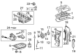
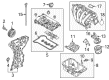
OEM Scion Throttle Body
Fuel Injection Throttle Body- Select Vehicle by Model
- Select Vehicle by VIN
Select Vehicle by Model
orMake
Model
Year
Select Vehicle by VIN
For the most accurate results, select vehicle by your VIN (Vehicle Identification Number).
10 Throttle Bodies found


Scion Throttle Body Part Number: 22030-0V010
$318.97 MSRP: $455.41You Save: $136.44 (30%)Ships in 1 Business DayProduct Specifications- Other Name: Body Assembly, Throttle; Fuel Injection Throttle Body; ETB Assembly; Body Assembly, Throttle W/Throttle Position Sensor
- Replaces: 22030-36010


Scion Throttle Body Part Number: 22210-21020
$376.47 MSRP: $551.72You Save: $175.25 (32%)Ships in 1-2 Business DaysProduct Specifications- Other Name: Body Assembly, Throttle


Scion Throttle Body Part Number: 22030-0H021
$385.66 MSRP: $565.19You Save: $179.53 (32%)Ships in 1-3 Business DaysProduct Specifications- Other Name: Body Assembly, Throttle; Fuel Injection Throttle Body; ETB Assembly
- Replaces: 22030-28060, 22030-28061, 22030-0H020


Scion Throttle Body Part Number: 22030-0T080
$318.97 MSRP: $455.41You Save: $136.44 (30%)Ships in 1-3 Business DaysProduct Specifications- Other Name: Body Assembly, Throttle; Fuel Injection Throttle Body; ETB Assembly
- Replaces: 22030-37050
Scion Throttle Body Part Number: 22030-0T130
$317.45 MSRP: $453.25You Save: $135.80 (30%)Ships in 1-3 Business DaysProduct Specifications- Other Name: Body Assembly, Throttle
- Manufacturer Note: (L)
- Replaces: 22030-37040

Scion Throttle Body Part Number: 22030-0H031
$348.56 MSRP: $497.66You Save: $149.10 (30%)Ships in 1-3 Business DaysProduct Specifications- Other Name: Body Assembly, Throttle; Fuel Injection Throttle Body; ETB Assembly; Body Assembly, Throttle W/Throttle Position Sensor
- Manufacturer Note: (L)
- Replaces: 22030-28070, 22030-28071, 22030-0H030
Scion Throttle Body Part Number: 22030-47020
$354.34 MSRP: $519.28You Save: $164.94 (32%)Ships in 1-2 Business DaysProduct Specifications- Other Name: Body Assembly, Throttle; Fuel Injection Throttle Body Assembly; Fuel Injection ETB Assembly; Body Assembly, Throttle W/Throttle Position Sensor

Scion Throttle Body Part Number: 22030-WB001
$310.03 MSRP: $442.65You Save: $132.62 (30%)Ships in 1-3 Business DaysProduct Specifications- Other Name: Body Assembly, Throttle; Body Assembly, Throttle W/Throttle Position Sensor
Scion Throttle Body Part Number: SU003-00313
$424.83 MSRP: $579.02You Save: $154.19 (27%)Ships in 1-3 Business DaysProduct Specifications- Other Name: Chm Assembly-Electrical Throttle; Fuel Injection Throttle Body Assembly; Fuel Injection ETB Assembly; Body Assembly, Throttle W/Throttle Position Sensor

Scion Throttle Body Part Number: 22030-37020
$355.36 MSRP: $520.78You Save: $165.42 (32%)Product Specifications- Other Name: Body Assembly, Throttle
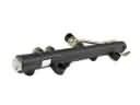
Scion Throttle Body
OEM parts deliver unmatched quality you can rely on. They pass extensive quality control inspections. Scion produces them to the official factory specifications. This process helps prevent defects and imperfections. So you can get exceptional lifespan and a flawless fit. Need new OEM Scion Throttle Body? You'll love our wide selection of genuine options. Shop in minutes and skip the hunt. Our prices are unbeatable, you'll save time and money. It's easy to shop and find the right piece. Our committed customer service team gives professional help from start to finish. Every part includes a manufacturer's warranty. We ship quickly, your parts will arrive fast at your door.
Scion Throttle Body controls the incoming air faster, which provides the drivers with sharper reaction of the pedal and a smoother power. In 2003, Scion hit the streets with small rides that avoided the bargaining table, cars that screamed with bright paint, and a car customization approach encouraging first-time car buyers to design cars their own way, a tactic that was enhanced by the use of online worlds such as virtual Scion City and limited Release Series drops that made the process of buying a car feel like winning a collectible, and the attitude that played well in the showrooms long after the first year of its debut. It has succeeded by being the experimental laboratory of Toyota, showcasing new sales concepts, music tours and pop-up art events, which resonated with the young drivers, selling more than 1,000,000 units until 2016, and even after the badge is no longer on sale its legacy lives on in how mainstream cars now offer no-haggle prices, brash colors and customization right off-the-factory. The Throttle Body fits in between the intake tube and manifold in any modern Scion, and the Throttle Body consists of an electronic butterfly which swivels in milliseconds with the movement of the accelerator, substituting the bulky cables with clear signals which smooth emissions, sharpen revs, and allow the engine to inject just the right amount of air to sustain even cruising and launches of undeniable power. The payoff is felt by the drivers every time they press the pedal as the Throttle Body speaks immediately with the fuel injection to adjust the air mixture and a performance upgrade of the Throttle Body simply drops in on any Scion and lets it open to throttle at a faster rate, have a cleaner idle and last longer on well established hardware.
Scion Throttle Body Parts and Q&A
- Q: How to service and repair the throttle body on Scion tC?A:The service and repair work on throttle bodies begins with draining engine coolant followed by disconnection of the negative battery terminal cable and maintenance of a 90-second wait before proceeding. Start repairs by first unscrewing the 2 engine cover nuts and then disconnecting power wires from the mass air flow meter and purge VSV while you detach the wire harness clamp and disassemble the No. 2 ventilation hose, purge line hoses from throttle body and purge VSV, also remove the No. 1 air cleaner hose. To obtain access to the air cleaner assembly disconnect two hook clamps which then allows removal of the air cleaner cap followed by taking out the air cleaner filter element. To access the throttle body first disconnect the water by-pass hoses as well as the No. 1 throttle body hose and throttle position sensor and control motor connector and afterward remove the wire harness clamp and fuel tube from its place. Begin the procedure by removing the 4 bolts from the fuel pipe support and throttle body whereafter removing the gasket on the intake manifold. Apply a new gasket to the intake manifold before securing the throttle body and fuel pipe clamp through 4 bolts tightened at 30 N.m (305 kgf.cm, 22 in.lbf). At the same time, insert the fuel tube into the clamp and install the wire harness clamp. At the correct angle position the paint mark and hose clamp during connection of the throttle position sensor and control motor connector and the No. 1 throttle body hose and the No. 2 water by-pass hose. Perform the same process for connecting the by-pass hose to its manifold. Place the air cleaner filter element with proper orientation onto the air cleaner case before inserting the hinge part of the air cleaner cap while hanging the two hook clamps. The alignment of the match marks on the No. 1 air cleaner hose and throttle body must be accomplished before the hose is connected and the No. 1 air cleaner clamp is unfastened to maintain proper hose clamp positioning. The purge VSV with its hose should connect to the throttle body along with the purge line hose. At the same time the No. 2 ventilation hose must link to the cylinder head cover while maintaining correct positioning for all paint marks and hose clamps. Mount the wire harness clamp then link both the purge VSV connector and the mass air flow meter connector. The cable connections to the negative battery terminal should be reestablished followed by engine coolant addition while confirming no coolant escape occurs. After installation of the engine cover the final step involves torquing the 2 nuts to 7.0 N.m (71 kgf.cm, 62 in.lbf) while specific systems need initialization after battery terminal removal.
- Q: How to service and repair the throttle body on Scion xB?A:Service and repair operations on the throttle body must begin with disconnecting the negative battery cable for at least 90 seconds to avoid triggering Air Bag and seat belt pretensioners. The air cleaner assembly requires the MAF meter connector and purge VSV connector separation followed by wire harness clamp detachment and purging of both No. 2 and No. 1 line hoses and ventilation hose. Drain the engine coolant and slide the clamp hooks open before loosening the hose clamp to remove the air cleaner case and filter element along with its 4 bolts. Proceed by loosening the nut which enables the accelerator control cable disconnect. The installation of automatic transaxle requires disconnecting the throttle position sensor connector and removing the transmission oil filler tube along with its O-ring. Begin by removing the connection of IAC valve and throttle position sensor cords (manual transaxle only), next follow steps to disconnect the wire harness clamp and take away the throttle body and accelerator control cable bracket by extracting the bolt and 2 nuts (intake manifold gasket removal not required). The installation requires users to connect the No. 1 and No. 2 water by-pass hoses followed by inserting a new gasket into the intake manifold and securing the throttle body along with accelerator control bracket using a bolt and 2 nuts at 30 N.m (306 kgf.cm, 22 ft.lbf) torque rating before completing the process with wire harness clamp installation and throttle position sensor and IAC valve connector establishment. The transmission oil filler tube subassembly procedure requires new installation of an O-ring on the transmission oil filler tube and a bolt torque of 5.5 N.m (56 kgf.cm, 49 in.lbf) followed by connecting the hose and throttle position sensor and inserting the oil dipstick. Install the accelerator control cable assembly, torqued to 13 N.m (133 kgf.cm, 10 ft.lbf), followed by the air cleaner assembly, securing the air cleaner case to the air cleaner bracket with 3 bolts torqued to 7.8 N.m (80 kgf.cm, 69 in.lbf), connecting the air cleaner inlet to the engine compartment with a bolt torqued to 7.5 N.m (76 kgf.cm, 66 in.lbf), tightening the hose clamp, and reconnecting the MAF meter and purge VSV connectors, attaching the wire harness clamp, and connecting the No. 2 and No. 1 purge line hoses and ventilation hose, then locking the 2 clamp hooks. The end step includes attaching the cable to the negative battery terminal followed by engine coolant addition and a search for any engine coolant leakage.