×
ToyotaParts- Hello
- Login or Register
- Quick Links
- Live Chat
- Track Order
- Parts Availability
- RMA
- Help Center
- Contact Us
- Shop for
- Toyota Parts
- Scion Parts
My Garage
My Account
Cart
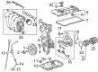
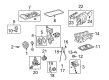
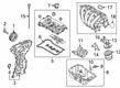
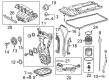
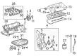
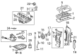
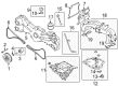
OEM Scion Intake Manifold
Engine Intake Manifold- Select Vehicle by Model
- Select Vehicle by VIN
Select Vehicle by Model
orMake
Model
Year
Select Vehicle by VIN
For the most accurate results, select vehicle by your VIN (Vehicle Identification Number).
11 Intake Manifolds found


Scion Intake Manifold Part Number: 17120-0T080
$280.87 MSRP: $401.02You Save: $120.15 (30%)Ships in 1-2 Business DaysProduct Specifications- Other Name: Manifold Assembly, Intake; Engine Intake Manifold; Manifold, Intake
- Manufacturer Note: (L)
- Replaces: 17120-37031


Scion Intake Manifold Part Number: 17120-0T011
$305.92 MSRP: $436.78You Save: $130.86 (30%)Ships in 1-3 Business DaysProduct Specifications- Other Name: Manifold Assembly, Intake; Engine Intake Manifold; Manifold, Intake
- Replaces: 17120-0T010, 17120-37020, 17120-37021
Scion Intake Manifold Part Number: 17120-0T012
$221.57 MSRP: $316.35You Save: $94.78 (30%)Ships in 1-2 Business DaysProduct Specifications- Other Name: Manifold Assembly, Intake; Engine Intake Manifold; Manifold, Intake
- Replaces: 17120-37022

Scion Intake Manifold Part Number: 17120-WB002
$276.86 MSRP: $395.30You Save: $118.44 (30%)Ships in 1-3 Business DaysProduct Specifications- Other Name: Manifold Assembly, Intake; Engine Intake Manifold; Manifold, Intake

Scion Intake Manifold Part Number: 17120-36021
$781.55 MSRP: $1145.38You Save: $363.83 (32%)Ships in 1-3 Business DaysProduct Specifications- Other Name: Manifold Assembly, Intake; Engine Intake Manifold; Manifold, Intake
- Replaces: 17120-36020

Scion Intake Manifold Part Number: 17120-21020
$212.02 MSRP: $302.71You Save: $90.69 (30%)Ships in 1-2 Business DaysProduct Specifications- Other Name: Manifold Assembly, Intake; Engine Intake Manifold; Manifold, Intake
- Replaces: 17101-21030

Scion Intake Manifold Part Number: 17120-28101
$323.28 MSRP: $461.56You Save: $138.28 (30%)Ships in 1-3 Business DaysProduct Specifications- Other Name: Manifold Assembly, Intake; Engine Intake Manifold
- Replaces: 17120-28090, 17120-28100
Scion Intake Manifold Part Number: 17120-0H081
$336.09 MSRP: $479.86You Save: $143.77 (30%)Product Specifications- Other Name: Manifold Assembly, Intake; Engine Intake Manifold; Manifold, Intake
- Manufacturer Note: (L)
- Replaces: 17120-28170, 17120-0H080

Scion Intake Manifold Part Number: SU003-00288
$254.39 MSRP: $337.78You Save: $83.39 (25%)Ships in 1-3 Business DaysProduct Specifications- Other Name: Manifold Complete-Intake; Engine Intake Manifold; Manifold, Intake


Scion Intake Manifold Part Number: 17120-47061
$172.67 MSRP: $244.43You Save: $71.76 (30%)Ships in 1-3 Business DaysProduct Specifications- Other Name: Manifold Assembly, Intake; Manifold, Intake
Scion Intake Manifold Part Number: 17120-47060
$201.91 MSRP: $288.27You Save: $86.36 (30%)Ships in 1-3 Business DaysProduct Specifications- Other Name: Manifold Assembly, Intake; Manifold, Intake
Scion Intake Manifold
OEM parts deliver unmatched quality you can rely on. They pass extensive quality control inspections. Scion produces them to the official factory specifications. This process helps prevent defects and imperfections. So you can get exceptional lifespan and a flawless fit. Need new OEM Scion Intake Manifold? You'll love our wide selection of genuine options. Shop in minutes and skip the hunt. Our prices are unbeatable, you'll save time and money. It's easy to shop and find the right piece. Our committed customer service team gives professional help from start to finish. Every part includes a manufacturer's warranty. We ship quickly, your parts will arrive fast at your door.
The Scion Intake Manifold directs the cool and even airflow to drive the engines in a powerful and speedy manner. Scion came to American roads in 2003 with a mission of appealing to the drivers who needed style, good value, and no nonsense pricing in fast fun packs. The brand bypassed traditional hype and created a large virtual Scion City in which customers have built cars as they relax in their hostels. Scion continued to keep the excitement high as it released a limited number of Release Series machines that were painted in blaring colors making the parking lots look like rolling festivals. Purchasing remained easy since all the stickers displayed a single price and dealers were giving out swag rather than upsell scripts. Scion is also an experiment table that allowed Toyota to test aggressive paint, whimsical interior technology, and bare-bones trim and scale to the rest of the fleet. Online fans continue to share tales of first cars that showed them how customization could be affordable and theirs. Within the engine bay, the Intake Manifold divides the incoming air into identical and equally high-velocity streams, which strike each cylinder at well-timed and consistent angles in order to provide constant power. It is created using lightweight composite plastic to ensure that the heat is low so that oxygen is dense and the combustion is harder. Variable length Intake Manifold (when applied in sudden throttle sweeps) shortens runners to provide at least partial launch power and lengthens runners to sustain top-end hunger. Since a free flowing air burns fuel more efficiently, the Intake Manifold causes the mileage to sneeze as the tachometer scaled higher without hacking.
Scion Intake Manifold Parts and Q&A
- Q: How to remove the intake manifold on Scion xB?A:The removal process of 2AZ-FE engine intake manifold starts with clearing fuel system pressure. The specific order for removal includes clearing the windshield wiper arm position cover then disconnecting the both left and right front wiper arm and blade assemblies. Next remove the hood to cowl top seal followed by the cowl top ventilator louvers from both sides. Once those parts are removed from the list, proceed to remove the front wiper motor as well as link and outer cowl top panel and No.1 engine cover sub-assembly and air cleaner cap sub-assembly with its connected No.1 air cleaner hose. Begin by taking out the throttle body assembly then break the connection between the fuel tube sub-assembly through the process of removing the EFI fuel pipe clamp followed by disconnecting the fuel tube. The service starts by disconnecting three connectors including the injector connector and camshaft oil control valve connector and air fuel ratio sensor connector from the fuel delivery pipe sub-assembly with fuel tube sub-assembly followed by wire harness and fuel tube sub-assembly separation. Two bolts need removal before separating the delivery pipe sub-assembly together with the No. 1 delivery pipe spacer and four insulators from the cylinder head. The procedure ends with ventilation hose and union to connector tube hose disconnection before removing the five bolts and two nuts that detach the intake manifold. Finish by taking off the ventilation hose, vacuum hose clamp bolt, and union to connector tube hose together with the throttle hose.
- Q: How to install the intake manifold and associated components on Scion xD?A:The installation begins with setting a fresh gasket on the manifold before tightening the 4 bolts and 2 nuts of the intake manifold and intake manifold stay to 28 Nm torque (286 kgf-cm, 21 ft-lbf). The ventilation hose needs to be attached and 4 wire harness clamps need installation. The installation of the throttle body assembly should follow the transmission oil level gauge sub-assembly installation. Install the bolt using 5.5 Nm force (56 kgf-cm or 49 in-lbf) and connect the breather hose together with the dipstick. Mount the oil cooler tube clamp before inserting both outlet No.1 and inlet No.1 oil cooler tubes into the oil cooler tube union while tightening the transmission oil filler tube sub-assembly bolt at 5.5 Nm (56 kgf-cm, 49 in-lbf). You can install the outlet No. 1 oil cooler tube by using a union nut wrench to tighten it to 34 Nm (347 kgf-cm, 25 ft-lbf) although 32 Nm (327 kgf-cm, 24 ft-lbf) is also acceptable using the union wrench while the nut is parallel to the torque wrench. Apply the same installation procedure to the inlet No. 1 oil cooler tube. The necessary installation sequence includes engine oil level dipstick followed by starter assembly and flywheel housing side cover after which comes the injector vibration insulator and the No. 1 delivery pipe spacer and fuel delivery pipe sub-assembly along with the fuel tube sub-assembly and fuel pipe clamp. Next in order come the vacuum hose together with No. 1 fuel vapor feed hose and harness bracket and engine wire harness and lastly the air cleaner cap sub-assembly with hose. The cable installation to the negative battery terminal requires a torque setting of 5.4 Nm (55 kgf-cm, 48 in-lbf) and after completing the add procedure of engine coolant you must inspect for coolant and fuel leaks then place the No. 2 cylinder head cover in position followed by securing engine under covers on both sides with torques of 5.0 Nm (51 kgf-cm, 44 in-lbf) each.