×
ToyotaParts- Hello
- Login or Register
- Quick Links
- Live Chat
- Track Order
- Parts Availability
- RMA
- Help Center
- Contact Us
- Shop for
- Toyota Parts
- Scion Parts
My Garage
My Account
Cart
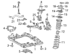
OEM Scion Front Cross-Member
Front Engine Cross Member- Select Vehicle by Model
- Select Vehicle by VIN
Select Vehicle by Model
orMake
Model
Year
Select Vehicle by VIN
For the most accurate results, select vehicle by your VIN (Vehicle Identification Number).
20 Front Cross-Members found


Scion Front Crossmember Part Number: 57104-47020
$561.02 MSRP: $822.18You Save: $261.16 (32%)Ships in 1 Business DayProduct Specifications- Other Name: Member Sub-Assembly, Front; Suspension Subframe Crossmember, Front; Crossmember; Member Sub-Assembly, Front Cross
- Position: Front

Scion Suspension Crossmember, Front Part Number: SU003-00348
$304.01 MSRP: $403.67You Save: $99.66 (25%)Ships in 1-3 Business DaysProduct Specifications- Other Name: Cross Member Complete Front; Suspension Subframe Crossmember, Front; Crossmember; Member Sub-Assembly, Front Cross
- Position: Front

Scion Lower Crossmember, Front Part Number: 57104-21041
$401.55 MSRP: $588.48You Save: $186.93 (32%)Ships in 1-3 Business DaysProduct Specifications- Other Name: Member Sub-Assembly, Front; Radiator Support Panel Reinforcement, Front Lower; Member Sub-Assembly, Front Cross
- Position: Front
- Replaces: 57104-21040

Scion Engine Cradle Part Number: 51201-WB001
$423.18 MSRP: $620.18You Save: $197.00 (32%)Ships in 1-3 Business DaysProduct Specifications- Other Name: Crossmember Sub-Assembly; Crossmember; Crossmember Sub-Assembly, Front Suspension

Scion Crossmember, Front Part Number: 57103-74011
$459.92 MSRP: $674.02You Save: $214.10 (32%)Ships in 1-3 Business DaysProduct Specifications- Other Name: Crossmember Sub-Assembly; Cowl Crossmember; Crossmember, Front
- Position: Front

Scion Front Crossmember Part Number: 57104-12270
$595.75 MSRP: $873.08You Save: $277.33 (32%)Ships in 1-3 Business DaysProduct Specifications- Other Name: Member Sub-Assembly, Front; Fender Rail Reinforcement Brace; Suspension Subframe Crossmember; Engine Mount Crossmember; Support Brace; Crossmember; Member Sub-Assembly, Front Cross
- Position: Front

Scion Engine Cradle Part Number: 51201-52014
$859.52 MSRP: $1259.64You Save: $400.12 (32%)Ships in 1-3 Business DaysProduct Specifications- Other Name: Crossmember Sub-Assembly; Engine Cradle, Front; Crossmember Sub-Assembly, Front Suspension
Scion Engine Cradle Part Number: 51201-52013
$917.97 MSRP: $1345.28You Save: $427.31 (32%)Ships in 1-3 Business DaysProduct Specifications- Other Name: Crossmember Sub-Assembly; Engine Cradle, Front; Crossmember Sub-Assembly, Front Suspension
- Replaces: 51201-52011, 51201-52010, 51201-52012

Scion Suspension Crossmember, Front Part Number: 51201-52097
$923.54 MSRP: $1353.45You Save: $429.91 (32%)Ships in 1-3 Business DaysProduct Specifications- Other Name: Crossmember Sub-Assembly; Suspension Subframe Crossmember, Front; Crossmember Sub-Assembly, Front Suspension
- Position: Front
- Replaces: 51201-52094, 51201-52090, 51201-52092, 51201-52095, 51201-52093, 51201-52096

Scion Crossmember Sub-Assembly Part Number: 51201-78010
$1003.44 MSRP: $1470.55You Save: $467.11 (32%)Ships in 1-3 Business DaysProduct Specifications- Other Name: CROSSMEMBER SUB-ASSY
- Position: Front
- Replaces: 51201-12441, 51201-42070, 51201-12442, 51201-42071

Scion Engine Cradle Part Number: 51201-21060
$1095.94 MSRP: $1606.12You Save: $510.18 (32%)Ships in 1-3 Business DaysProduct Specifications- Other Name: Crossmember Sub-Assembly; Suspension Subframe Crossmember, Front; Crossmember; Crossmember Sub-Assembly, Front Suspension

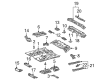
Scion Front Crossmember, Driver Side Part Number: 57452-52903
$125.56 MSRP: $177.74You Save: $52.18 (30%)Ships in 1-3 Business DaysProduct Specifications- Other Name: Member Sub-Assembly, Front Floor; Floor Pan Crossmember, Front Left
- Position: Front Driver Side
- Replaces: 57452-52905

Scion Crossmember Extension, Passenger Side Part Number: 57453-WB001
$54.59 MSRP: $75.98You Save: $21.39 (29%)Ships in 1-3 Business DaysProduct Specifications- Other Name: Member, Front Floor Cross Member; Floor Pan Crossmember Bracket, Right; Member, Front Floor Cross Side, Passenger Side
- Position: Passenger Side
Scion Crossmember Extension, Driver Side Part Number: 57454-WB001
$57.14 MSRP: $79.54You Save: $22.40 (29%)Ships in 1-3 Business DaysProduct Specifications- Other Name: Member, Front Floor Cross Member; Floor Pan Crossmember Bracket, Left; Member, Front Floor Cross Side, Driver Side
- Position: Driver Side

Scion Floor Crossmember, Passenger Side Part Number: 57453-52020
$68.67 MSRP: $96.40You Save: $27.73 (29%)Ships in 1-3 Business DaysProduct Specifications- Other Name: Floor Pan Crossmember, Right; Member, Front Floor Cross Side, Passenger Side
- Position: Passenger Side
Scion Floor Crossmember, Driver Side Part Number: 57454-52010
$69.39 MSRP: $97.40You Save: $28.01 (29%)Ships in 1-3 Business DaysProduct Specifications- Other Name: Floor Pan Crossmember, Left; Member, Front Floor Cross Side, Driver Side
- Position: Driver Side

Scion Front Crossmember, Driver Side Part Number: 57452-52081
$102.86 MSRP: $144.38You Save: $41.52 (29%)Ships in 1-3 Business DaysProduct Specifications- Other Name: Member, Front Floor Cross Member; Floor Pan Crossmember, Front Left, Left; Crossmember; Member, Front Floor Cross, Driver Side; Member, Front Floor Cross
- Position: Driver Side

Scion Floor Crossmember, Driver Side Part Number: 57454-52012
$104.09 MSRP: $146.10You Save: $42.01 (29%)Ships in 1-3 Business DaysProduct Specifications- Other Name: Member, Front Floor Cross Member; Floor Pan Crossmember, Front Left; Reinforcement; Member, Front Floor Cross Side, Driver Side
- Position: Driver Side
- Replaces: 57454-52011
Scion Floor Crossmember, Passenger Side Part Number: 57453-52022
$104.09 MSRP: $146.10You Save: $42.01 (29%)Ships in 1-3 Business DaysProduct Specifications- Other Name: Member, Front Floor Cross Member; Floor Pan Crossmember, Front Right; Reinforcement; Member, Front Floor Cross Side, Passenger Side
- Position: Passenger Side
- Replaces: 57453-52021

Scion Engine Cradle, Front Part Number: 51100-74022
$1209.90 MSRP: $1773.12You Save: $563.22 (32%)Product Specifications- Other Name: Frame Assembly, Front; Engine Cradle, Front; Crossmember
- Position: Front
- Replaces: 51100-74021
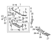
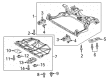
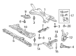
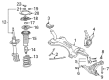
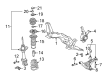
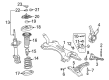
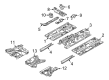
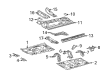
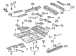
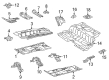
Scion Front Cross-Member
OEM parts deliver unmatched quality you can rely on. They pass extensive quality control inspections. Scion produces them to the official factory specifications. This process helps prevent defects and imperfections. So you can get exceptional lifespan and a flawless fit. Need new OEM Scion Front Cross-Member? You'll love our wide selection of genuine options. Shop in minutes and skip the hunt. Our prices are unbeatable, you'll save time and money. It's easy to shop and find the right piece. Our committed customer service team gives professional help from start to finish. Every part includes a manufacturer's warranty. We ship quickly, your parts will arrive fast at your door.
Scion Front Cross-Member enhances the chassis strength which allows the compact rides to corner hard without shaking flex. Scion succeeded on the basis of abandoning the dealership stuffiness and plain pricing and bold paint to the young drivers. First buyers were drawn to Scion through eccentric Release Series drops that were more sneaker-like launches than car ones. Scion was also applied to experiment on new gadgets and trims that Toyota applied before they were introduced into the mainstream market. Although the lineup shut down in 2016, Scion continues to be known by its short name of customizable small cars that perform larger than their size. Limited-run trims were speedy since shoppers were aware that they would be substituted the following season by a different color or badge. No frills one-price labels eliminate bargaining and allow friends to boast of their savings that were equal to their check. The Front Cross-Member, made of heavy stamped steel, supports the weight of the engine and transmission, attaches the arms of the suspension to an unchanging plane, and maintains the lower-body rails at right angles when the road sends potholes and abrupt sideways forces on the chassis. The Front Cross-Member will not twist, and thus the input from steering is turned into sharp direction changes rather than the mushy lag. The Front Cross-Member connects the important load paths, and since airbags are deployed during deployment, crumple zones do as well. Install a new Front Cross-Member as corrosion starts to creep and the car gets factory tight again without exotics.
Scion Front Cross-Member Parts and Q&A
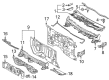
- Q: How to install the Front Cross-Member on Scion xD?A:You should start the front suspension member installation by attaching the front suspension member dumper weight through 2 bolts which need proper torque of 32 Nm (326 kgf-cm, 24 ft-lbf). The engine moving control rod requires installation through a bolt which must reach 100 Nm (1020 kgf-cm, 74 ft-lbf) torque once the transaxle side has been temporarily secured. The front lower suspension arm sub-assemblies for left and right sides should be temporarily tightened after installing 2 clips on the engine moving control rod cover. The installation sequence starts with front stabilizer bar followed by both front stabilizer brackets No.1 LH and RH. The same left-hand side protocol applies. Install the power steering gear onto the front suspension crossmember with 2 bolts combined with 2 nuts yet avoid allowing the nut to rotate as you torque them to 96 Nm (979 kgf-cm, 71 ft-lbf). Add a transmission jack under the front suspension crossmember to support it prior to utilizing six bolts for provisional attachment to the body. Specially designed 09670-00011 tool should enter datum holes of front suspension crossmembers RH and LH one at a time to torque bolts A, B, and C to 70 Nm (714 kgf-cm, 52 ft-lbf), 160 Nm (1631 kgf-cm, 118 ft-lbf), 95 Nm (969 kgf-cm, 70 ft-lbf) respectively when used vertically. After installing the engine control moving rod with 120 Nm bolt torque (1224 kgf-cm, 89 lbf) the technician must continue by installing both front lower suspension arm sub-assemblies with the same procedure. Repetition will prevail in your installation of the front stabilizer link assemblies and tie rod end sub-assemblies to both sides. Position the No. 1 steering column hole cover sub-assembly by securing clips around it first before placing the sliding yoke on the intermediate shaft according to matchmarks. Fasten this setup with a torque of 35 Nm (360 kgf-cm, 26 ft-lbf). The installation begins with attaching the column hole cover silencer sheet through two clips while placing the floor carpet and finishing with torquing the front wheel to 103 Nm (1050 kgf-cm, 76 ft-lbf). With both wheels facing forward keep the suspension stable while completing full torques on all front lower suspension arm sub-assembly units. Uphold the installation of the outer cowl top panel alongside the front air shutter seal on the right-hand side followed by windshield wiper motor and link, cowl top ventilator louvers for both left and right sides, hood to cowl top seal and front wiper arm assemblies (LH and RH with their respective front wiper arm head caps). Secure the hood sub-assembly using provisional bolt installation along with required adjustments to its position. The last steps include confirming straight front wheels before checking both ABS speed sensor signals and VSC sensor signals and performing front wheel alignment inspection and adjustments.