×
ToyotaParts- Hello
- Login or Register
- Quick Links
- Live Chat
- Track Order
- Parts Availability
- RMA
- Help Center
- Contact Us
- Shop for
- Toyota Parts
- Scion Parts
My Garage
My Account
Cart
OEM Scion xD Front Cross-Member
Front Engine Cross Member- Select Vehicle by Model
- Select Vehicle by VIN
Select Vehicle by Model
orMake
Model
Year
Select Vehicle by VIN
For the most accurate results, select vehicle by your VIN (Vehicle Identification Number).
5 Front Cross-Members found

Scion xD Suspension Crossmember, Front Part Number: 51201-52097
$923.54 MSRP: $1353.45You Save: $429.91 (32%)Ships in 1-3 Business Days
Scion xD Floor Crossmember, Passenger Side Part Number: 57453-52020
$68.67 MSRP: $96.40You Save: $27.73 (29%)Ships in 1-3 Business DaysScion xD Floor Crossmember, Driver Side Part Number: 57454-52010
$69.39 MSRP: $97.40You Save: $28.01 (29%)Ships in 1-3 Business Days
Scion xD Floor Crossmember, Driver Side Part Number: 57454-52012
$104.09 MSRP: $146.10You Save: $42.01 (29%)Ships in 1-3 Business DaysScion xD Floor Crossmember, Passenger Side Part Number: 57453-52022
$104.09 MSRP: $146.10You Save: $42.01 (29%)Ships in 1-3 Business Days
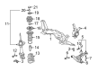
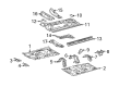
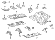
Scion xD Front Cross-Member
Choose genuine Front Cross-Member that pass strict quality control tests. You can trust the top quality and lasting durability. Shopping for OEM Front Cross-Member for your Scion xD? Our website is your one-stop destination. We stock an extensive selection of genuine Scion xD parts. The price is affordable so you can save more. It only takes minutes to browse and find the exact fit. Easily add to cart and check out fast. Our hassle-free return policy will keep you stress-free. We process orders quickly for swift delivery. Your parts will arrive faster, so you can get back on the road sooner.
The Scion xD Front Cross-Member plays a key role in stabilizing vehicles within the Scion xD model range by ensuring reliability and performance. As a fundamental reinforcement component the Front Cross-Member performs as the main support for the engine and transmission which keeps vehicles stable and delivers superior handling capabilities. The steel structure of this component resists both heavy loads while handling torsional strength that stops body panel misalignment through twisting forces. This piece plays an essential role for safety alongside performance in the Scion xD chassis framework because of its reliability. The Front Cross-Member delivers identical durability standards when applied with all models in the xD family. The innovative design of the Front Cross-Member improves vehicle efficiency because it strengthens the vehicle structure which results in a combined highway rating of 33 mpg and city rating of 27 mpg in the Scion xD model. The automotive safety features of the Scion car incorporate anti-lock brakes and multiple airbags which are strengthened through the dependable Front Cross-Member design. The automotive market recognizes the the automaker model Front Cross-Member because of its combined strength alongside reliability and remarkable performance which guarantees safe driving for diverse road situations.
Scion xD Front Cross-Member Parts and Q&A
- Q: How to install the Front Cross-Member on Scion xD?A:The first step to install the front suspension member involves attaching the front suspension member dumper weight through 2 bolts that need a torque of 32 Nm (326 kgf-cm 24 ft-lbf). When installing the engine moving control rod secure it with a bolt which requires 100 Nm torque (1020 kgf-cm, 74 ft-lbf) on automatic and manual transaxles while temporarily tightening the transaxle side before achieving final torque. The installation of the engine moving control rod cover requires application of 2 clips to secure it in position. Install the front stabilizer bar and brackets on both sides after intermediately tightening the front lower suspension sub-assembly bolts of the LH and RH sides. Screw two bolts into the power steering gear to the front suspension crossmember through two nuts following a torque requirement of 96 Nm (979 kgf-cm, 71 ft-lbf). Perform this operation while monitoring to prevent nut rotation. After securing the front suspension crossmember with a transmission jack install the 6 bolts temporarily then use Special Service Tool: 09670-00011 to tighten the resulting torques of 70 Nm (714 kgf-cm, 52 ft-lbf), 160 Nm (1631 kgf-cm, 118 ft-lbf), and 95 Nm (969 kgf-cm, 70 ft-lbf) by inserting the tool vertically on bolts A, B, and C respectively. The engine moving control rod needs a bolt installed with torque set to 120 Nm (1224 kgf-cm, 89 ft-lbf). After this step install the front lower suspension arm sub-assemblies for both sides. The installer should then build both front stabilizer link assemblies and tie rod end sub-assemblies for either side. Fitting of the No. 1 steering column hole cover sub-assembly requires clipping installation while maintaining the lip free from damage. Stick to matchmarks and fix the steering sliding yoke to intermediate shaft by tightening it up to 35 Nm (360 kgf-cm, 26 ft-lbf). The floors require the column hole cover silencer sheet installed with two clips before applying the floor carpet. Fasten the front wheel while applying 103 Nm (1050 kgf-cm, 76 ft-lbf) of torque then aim both wheels straight ahead before stabilizing the suspension system. Both sides of front lower suspension arm sub-assemblies require full tightness. Integration of Parts includes the outer cowl top panel combined with front air shutter seal RH and windshield Wiper Motor alongside its link followed by cowl top ventilator louvers installation on both sides and completion with the hood to cowl top seal and front wiper arm assemblies to both sides that are equipped with front wiper arm head caps. Use 4 bolts to fasten the hood sub-assembly provisionally while inspecting the hood for adjustments according to manufacturing specifications. To finish the procedure use a straightedge on the front wheels before inspecting and adjusting the front wheel alignment and testing the VSC sensor signal.
- Q: How to remove the front cross-member on Scion xD?A:The first step to remove the front cross-member is to set front wheels in a straight-ahead stance followed by hood bolt removal. Start by taking off the front wiper arm head cap and proceed with removal of left and right front wiper arm assemblies including their blades. Uninstall the hood to cowl top seal and the left and right cowl top ventilator louvers. Remove the windshield Wiper Motor and link together with the right front air shutter seal as well as the outer cowl top panel. The column hole cover silencer sheet requires removal by first removing floor carpet then releasing two clips. Fixing the Steering Wheel assembly with a Seat Belt while marking the sliding yoke lets technicians separate the steering sliding yoke sub-assembly through bolt A loosening and bolt B removal of the steering intermediate shaft assembly. Start by removing clip A from the body along with separating clip B from the body to remove the No. 1 steering column hole cover sub-assembly. Use the same method to sever the left and right tie rod end sub-assemblies after removing the front wheel. Proceed with separating the left and right front stabilizer link assemblies through the identical approach used previously followed by left and right front lower suspension arm sub-assembly disconnection. The two hangers (Engine Hanger No. 1: 12281-37020, Engine Hanger No. 2: 12282-37010) must be installed in the correct direction before hooking up an engine chain hoist to them for suspension of the engine assembly. Avoid suspending by any other part. Start by removing the bolt that attaches the engine moving control rod which enables separation of the rod from the crossmember then support the crossmember with a transmission jack before proceeding to remove the 6 bolts. unsubscribe the power steering gear by removing its two bolts as well as two nuts while preventing the nut from rotating. The removal of front stabilizer No. 1 brackets on both sides will proceed in a single manner before handling the front stabilizer bar itself. Other side performs the same method of removing front lower suspension arm sub-assembly. Take out the 2 clips from the engine moving control rod cover and then remove engine moving control rod from automatic and manual transaxles by unboltting them. The procedure ends by removing the front suspension member dumper weight after taking away its 2 bolts.