×
ToyotaParts- Hello
- Login or Register
- Quick Links
- Live Chat
- Track Order
- Parts Availability
- RMA
- Help Center
- Contact Us
- Shop for
- Toyota Parts
- Scion Parts
My Garage
My Account
Cart
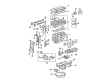
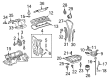
OEM Toyota Prius Timing Chain
Engine Timing Chain- Select Vehicle by Model
- Select Vehicle by VIN
Select Vehicle by Model
orMake
Model
Year
Select Vehicle by VIN
For the most accurate results, select vehicle by your VIN (Vehicle Identification Number).
4 Timing Chains found


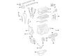
Toyota Prius Timing Chain Part Number: 13506-0T020
$217.84 MSRP: $311.03You Save: $93.19 (30%)


Toyota Prius Timing Chain Part Number: 13507-28010
$92.18 MSRP: $129.39You Save: $37.21 (29%)Ships in 1-2 Business Days
Toyota Prius Timing Chain Part Number: 13506-21050
$209.11 MSRP: $298.55You Save: $89.44 (30%)Ships in 1-3 Business Days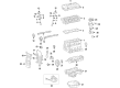
Toyota Prius Chain Sub-Assembly Part Number: 13506-37070
Toyota Prius Timing Chain
Choose genuine Timing Chain that pass strict quality control tests. You can trust the top quality and lasting durability. Shopping for OEM Timing Chain for your Toyota Prius? Our website is your one-stop destination. We stock an extensive selection of genuine Toyota Prius parts. The price is affordable so you can save more. It only takes minutes to browse and find the exact fit. Easily add to cart and check out fast. Our hassle-free return policy will keep you stress-free. We process orders quickly for swift delivery. Your parts will arrive faster, so you can get back on the road sooner.
Toyota Prius Timing Chain Parts and Q&A
- Q: How to install the timing chain on Toyota Prius?A:The proper starting position for the timing chain installation of the 1NZ-FXE engine requires setting No. 1 cylinder to 20 degrees ATDC and placing the crankshaft within 40 to 140 degrees ATDC range with all camshaft timing sprockets set to 20 degrees ATDC. Install the crankshaft between 40 and 140 to ensure 20 degrees ATDC topping point. The no. 1 cylinder should be set to 20 degrees ATDC and both intake and exhaust camshaft timing sprockets should be measured at 20 degrees ATDC marks should be set on the crankshaft before the reset. ATDC. ATDC before resetting the crankshaft to 20 degrees ATDC. To install the chain vibration damper apply 2 bolts that need 9.0 Nm (92 kgf-cm, 80 in-lbf) torque. Afterwards, position the timing marks on the camshaft timing sprocket and camshaft timing gear and crankshaft timing sprocket to match the yellow-marked timing chain. Finally, tighten the chain tensioner slipper with a bolt at the same torque value. After moving the stopper plate you need to free the plunger while pressing it inside before dropping the stopper plate to lock the plunger and insert a 3.0 mm (0.118 in.) diameter bar through the stopper plate hole followed by securing it with 2 bolts at 9.0 Nm (92 kgf-cm, 80 in-lbf). The installation process begins with tension checks between the intake and exhaust camshaft timing sprockets followed by the sequence of oil pump seal then timing chain cover then Crankshaft Position Sensor and lastly the camshaft timing oil control valve assembly. First, install the engine mounting bracket using 4 bolts at 55 Nm torque and then place the engine mounting spacer with 2 bolts at the same torque before installing the engine mounting insulator RH with 3 bolts and 4 nuts at 52 Nm torque. Position the straight pin hole of the crankshaft damper accurately and install the pulley while using Special Service Tool: 09213-58013 91111-50845 along with the tool to tighten the crankshaft bolt to 128 Nm (1,305 kgf-cm, 95 ft-lbf). Ensure the chain cover stays clear. After the Water Pump installation proceed with Drive Belt addition followed by checking the drive belt tension. You must install the purge VSV along with the cylinder head cover where you should use Toyota Genuine Seal Packing Black or Three Bond 1207B equivalent seal packing applied at two specified locations before installation of nine bolts and two nuts secured together at 10 Nm (102 kgf-cm, 7.4 ft-lbf). Safely attach the Ignition Coil as well as the brake master cylinder reservoir cover and wire harness before connecting the Fuel Injector along with ignition coil connectors. Equip the windshield washer jar with two bolts united by a specified torque then connect the reservoir bracket followed by the brake master cylinder reservoir and No. 2 air cleaner inlet and air cleaner assembly with correct torque specifications. The last manufacturing stages of assembly focus on installing the front cowl top panel outer, windshield Wiper Motor with wiper link assembly and cowl top ventilator louvers along with hood to cowl top seal and front wiper arms with wiper arm head caps. The last steps include attaching the negative battery terminal cable before installing both rear floor boards and engine coolant and leak inspection followed by support opening cover and under cover installation before proceeding with the front wheel mount and negative terminal initialization.

Related Toyota Prius Parts
 Toyota Prius Oil Drain Plug Gasket
 Toyota Prius Oil Pump
 Toyota Prius Camshaft
 Toyota Prius Camshaft Bearing
 Toyota Prius Crankshaft Thrust Washer
 Toyota Prius Cylinder Head Gasket
 Toyota Prius Harmonic Balancer
 Toyota Prius Oil Pan
 Toyota Prius Rocker Arm
 Toyota Prius Rod Bearing
 Toyota Prius Transmission Drain Plug
 Toyota Prius Valve Stem Seal