My Garage
Cart
Make sure this part fits

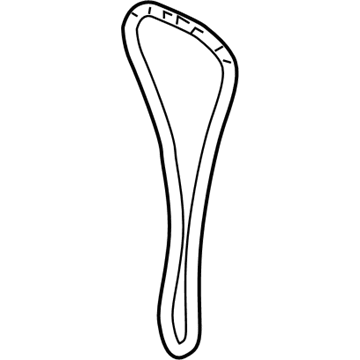
Toyota 13506-21050
Timing Chain

2000-2019 Toyota 1350621050

Customer Questions & Expert Answers (27)
Toyota 13506-21050 Timing Chain
  • Part Description
    Chain Sub-Assembly, Timing
  • Part Name Code
    13506
  • Manufacturer
    Toyota
Make sure this part fits
$209.11 MSRP: $298.55
You Save: $89.44 (30%)
Ships in 1-3 Business Days
1
ADD TO CART
  • Related Parts
  • Product Specifications
  • Vehicle Fitment
  • Customer Questions & Expert Answers
  • Product Specifications

    BrandGenuine Toyota
    Part Name Code13506
    Manufacturer Part Number13506-21050
    Part DescriptionChain Sub-Assembly, Timing
    Other NamesChain Sub-Assembly
    Item Dimensions6.3 x 3.3 x 1.2 inches
    Item Weight1.20 Pounds
    ConditionNew
    Fitment TypeDirect Replacement
    ManufacturerToyota
    SKU13506-21050
    WarrantyThis genuine Toyota part is guaranteed by Toyota's factory warranty.
    Shipping & ReturnShipping Policy Return Policy
    Warning: California's Proposition 65
  • Vehicle Fitment

    Year Make Model Trim Engine
    2004-2006 Scion xABase4 Cyl 1.5 L GAS
    2004-2006 Scion xBBase4 Cyl 1.5 L GAS
    2000-2005 Toyota EchoBase4 Cyl 1.5 L GAS
    2001-2009 Toyota PriusBase, Touring4 Cyl 1.5 L FULL HYBRID EV-GAS (FHEV)
    2012-2019 Toyota Prius CBase, Four, L, LE, One, Persona Series, Three, Two4 Cyl 1.5 L FULL HYBRID EV-GAS (FHEV)
    2007-2018 Toyota YarisBase, L, LE, S, SE4 Cyl 1.5 L GAS
  • Customer Questions & Expert Answers

    Q:
    Is 13506-21050 a good match for my car? Posted by ToyotaPartsNow Specialist
    A:
    Find out if part number 13506-21050 is the right fit for your car by Selecting Your Vehicle model.
    Posted by ToyotaPartsNow Specialist
    Q:
    How to replace the timing chain on Scion xA? Posted by Customer
    A:
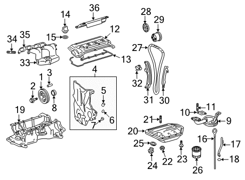
    The timing chain replacement process starts with removing the front wheel RH and then proceeding to uninstall the cylinder head cover No.2 by removing its 4 nuts. Commence by unscrewing four bolts that secure the ignition coil No.1 and draw forth the attached four ignition coils. Start by disconnecting both ventilation hoses then proceed to remove the cylinder head cover sub-assembly by uninstalling 9 bolts in addition to 2 nuts. Start by removing the fan together with the generator V-belt and generator assembly and engine under cover RH from the system. Eliminate engine fluid before proceeding to take out the vane pump V-belt along with the water pump pulley and water pump assembly. To access the crankshaft damper sub-assembly set the No.1 cylinder to TDC/compression and match the timing notch with timing mark "0" of the chain cover while keeping the camshaft timing sprocket and gear facing up; if alignment is off adjust the crankshaft 360 degrees so they match. The pulley bolt requires removal with Special Service Tool: 09213-58012 (91111-50845), 09330-00021, while Special Service Tool: 09950-50013 (09951-05010, 09952-05010, 09953-05020, 09954-05021) assists in taking out the damper. Remove the bolt and oil control valve as well as O-ring from the oil control valve connector. Beginning by placing a wooden block under the engine on a jack you should remove the liquid tube bolt holding the insulator before taking out five bolts and the nut. To proceed with the replacement start by unfastening 4 bolts from the engine mounting bracket RH and then unfasten the oil pump assembly along with its accompanying oil pump seal. Avoid crankshaft rotation when chain tensioner assembly No.1 is removed before pushing the plunger while raising the stopper plate upward then holding this plate with a 2.5 mm (0.098 inch) diameter bar. To remove the configuration begin by extracting the chain tensioner slipper and chain vibration damper No.1 from their positions before taking off the chain sub-assembly. To install the components set the crankshaft at ATDC 40 to 140 degrees first then set the intake and exhaust timing sprockets at ATDC 20 degrees before resetting the crankshaft to ATDC 20 degrees. Fasten the chain vibration damper with two bolts which require 9.0 Nm torque before aligning the sprocket matchmarks of the camshaft timing gear with the camshaft timing sprocket and crankshaft timing sprocket. Next, install the chain tensioner slipper (Torque: 9.0 Nm) followed by the chain tensioner (Torque: 9.0 Nm) and finally remove the holding bar from the chain tensioner to check the tension between the exhaust and intake camshaft timing sprockets. Begin installation with the oil pump seal by using Special Service Tool: 09950-60010 (09951-00250, 09951-00380, 09952-06010) combined with 09950-70010 (09951-07100) then install the oil pump assembly and water pump assembly. The procedure involves mounting the RH engine bracket with four bolts at 55 Nm torque strength while adding the RH insulator bracket through five bolts and one nut (A: 45 Nm, B: 52 Nm and C: 52 Nm) followed by liquid tube bolt attachment at 9.8 Nm torque value. Place the camshaft timing oil control valve assembly along with a new O-ring (Torque: 7.5 Nm), afterward install the crankshaft position sensor and water pump pulley through Special Service Tool: 09960-10010 (09962-01000, 09963-00600). The crankshaft damper sub-assembly requires installation with proper alignment of the pin hole toward its designated position while using a pulley bolt that reaches 128 Nm torque. Obtain seal packing (Part No 08826-00080 or equivalent) to apply on the cylinder head cover sub-assembly followed by installation of 9 bolts, 2 seal washers, and 2 nuts (Torque: 10 Nm), later install ignition coil No.1 (Torque: 9.0 Nm) and cylinder head cover No.2 (Nut A: 7.0 Nm, Bolt B: 7.0 Nm). End the process by putting back the generator assembly followed by vane pump V-belt and fan and generator V-belt. At this stage adjust the vane pump V-belt while checking the drive belt deflection and tension. The procedure ends with installing the new gasket on the oil pan drain plug (Torque: 38 Nm) while adding engine oil before leak inspection and engine coolant addition and leak inspection.
    Posted by ToyotaPartsNow Specialist
    Q:
    How to replace the timing chain on Scion xB? Posted by Customer
    A:
    You must start replacement of the timing chain by first taking out the front wheel RH and subsequently removing the 4 nuts from the cylinder head cover No. 2. Start by disconnecting ignition coil No.1 by pulling out its 4 ignition coils after removing their 4 securing bolts. The cylinder head cover sub-assembly can be taken out after removing 9 bolts combined with 2 nuts and disconnecting the ventilation hoses from both sides of the cover. The next step requires elimination of the fan and generator V-belt then removal of the generator assembly before proceeding with draining engine oil and coolant and removing engine under cover RH. The worker needs to align the timing marks and use Special Service Tools 09213-58012 (91111-50845), 09330-00021 to remove the crankshaft damper sub-assembly pulley bolt. The damper can be taken off with Special Service Tool: 09950-50013 (09951-05010, 09952-05010, 09953-05020, 09954-05021). Remove the oil control valve connector and its bolt and the valve along with the O-ring. Detach the crankshaft position sensor and engine mounting insulator sub-assembly RH by setting a wooden block on a jack under the engine before removing the bolt securing the liquid tube followed by taking 5 bolts and a nut along with the bolt fixing the mount pad. Start by removing the 4 bolts securing the transverse engine mounting bracket then proceed with taking out the oil pump assembly together with its seal. First rotate the camshaft counterclockwise 40 degrees from TDC before proceeding with removing chain tensioner assembly No. 1 while keeping the crankshaft from rotating due to the missing tensioner. Insert the plunger of the tensioner while using a 2.5 mm (0.098 inch) diameter bar for stable holding. The chain tensioner slipper and chain vibration damper Number One needs removal so you can pull out the disjointed chain components. Installation requires positioning the crankshaft to ATDC 40 to 140 degrees then correctly positioning the intake and exhaust timing sprockets at ATDC 20 degrees before resetting the crankshaft to ATDC 20 degrees. The chain vibration damper receives 2 bolts implemented with a torque of 9.0 Nm. Subsequently, align the matchmarks between the camshaft timing sprocket, camshaft timing gear, and crankshaft timing sprocket before installing the chain tensioner slipper and chain tensioner through bolts tightened to 9.0 Nm. Use the bar removed from the chain tensioner to measure the proper tension of the timing sprockets between intake and exhaust camshafts. Before installing the oil pump seal with Special Service Tool: 09950-60010 (09951-00250, 09951-00380, 09952-06010), 09950-70010 (09951-07100) you should place the oil pump assembly then the water pump assembly. Fit the transverse engine mounting bracket using 4 bolts at 55 Nm torque value followed by engine mounting insulator sub-assembly RH with 5 bolts and a nut where Bolt A receives 45 Nm torque and Bolt B achieves 52 Nm torque while Nut acquires 52 Nm torque then finish with a bolt installation of the liquid tube at 9.8 Nm torque value. Lay down the camshaft timing oil control valve assembly with its new O-ring first (Torque: 7.5 Nm) and afterward set the crankshaft position sensor and water pump pulley and crankshaft damper sub-assembly (Torque: 128 Nm). Seal packing (Part No. 08826-00080 or equivalent) needs application to the cylinder head cover sub-assembly before installation with 9 bolts and 2 seal washers and 2 nuts (Torque: 10 Nm). Reinstallation of ignition coil No. 1 (Torque: 9.0 Nm) and cylinder head cover No. 2 (Torque: 7.0 Nm) follows. Allow the generator assembly and the vane pump V-belt and the fan and generator V-belt to mount back into the system, conducting adjustments when required on both belts. The first step requires inspection of drive belt deflection and tension before installing the new gasket on the oil pan drain plug (Torque: 38 Nm) followed by engine under cover RH installation (Using 5.0 Nm torque for bolt and nut). After completing the tasks end with engine oil addition and leak inspection before adding engine coolant and confirming no coolant leakage.
    Posted by ToyotaPartsNow Specialist
    Q:
    How to service and repair the timing chain on Scion xB? Posted by Customer
    A:
    Before starting service and repair work on the timing chain disconnect the negative battery cable leaving it derouted for minimum ninety seconds to stop Air Bag deployment. The service requires removal of four nuts to access the No. 2 cylinder head cover followed by disassembly of the ignition coils then ventilator hose detachment from the cylinder head cover. After taking off the 9 bolts with two nuts the technician proceeds with removing the generator V belt then the generator followed by the engine under cover RH and draining the engine oil and coolant. Align the timing marks to remove the vane pump V belt, water pump pulley, water pump and crankshaft pulley using Special Service Tools: 09213-58012 (91111-50845), 09330-00021 when removing the pulley bolt. The removal of pulleys can be assisted with Special Service Tool: 09950-50013 (includes 09951-05010, 09952-05010, 09953-05020 and 09954-05021). Unplug the oil control valve connector while removing the bolt which leads to removal of the oil control valve with its O-ring. The crankshaft position sensor along with the engine mounting bracket insulator RH requires removal following engine support with a wooden block. After this, remove the mounting bracket RH. Two bolts must be removed from the timing chain cover and oil pump seal and No.1 chain tensioner. It is important to never rotate the crankshaft when you remove the chain tensioner while making sure the crankshaft faces a 40-degree counterclockwise angle from top dead center during camshaft rotation. Start the chain tensioner slipper removal before taking out the No. 1 chain vibration damper and the chain itself. You must set the No. 1 cylinder to 20 degrees ATDC for the installation process. installation of the chain vibration damper includes two bolts (torque at 9.0 Nm) while maintaining 20 degrees ATDC and placing the timing marks properly before setting the chain tensioner slipper and tensioner (torque at 9.0 Nm). The engine builder must perform a tension check between the sprockets before installing the oil pump seal and timing chain cover as well as water pump and engine mounting bracket RH (torque: 55 Nm) and engine mounting insulator RH (torque: 45 Nm for bolt A, 52 Nm for bolt B and nut). A new O-ring should accompany the camshaft timing oil control valve assembly for installation (torque: 7.5 Nm) together with the crankshaft position sensor and water pump pulley and crankshaft pulley (torque: 128 Nm using Special Service Tool: 09330-00021, 09213-58012 (91111-50845)). Seal packing (Part No. 08826-00080 or equivalent) goes onto the cylinder head cover before installing it with nine bolts using 2 seal washers and 2 nuts where torque is set to 10 Nm. Afterward, connect the No. 2 ventilation hose with the ventilation hose to the cylinder head cover. After installation of the ignition coils (9.0 Nm torque), put on the No. 2 cylinder head cover with 7.0 Nm torque for nuts A and B before adding the generator and vane pump V belt and generator V belt and final belt adjustment. The procedure includes checking drive belt tension along with installation of a new gasket on the oil pan drain plug (torque to 37.5 Nm) followed by engine oil addition and leak inspection and completion with coolant addition and negative battery terminal cable reconnection.
    Posted by ToyotaPartsNow Specialist
    Q:
    How to service the timing chain on Scion xA? Posted by Customer
    A:
    Service operations must begin by disconnecting the negative battery cable and waiting for 90 seconds or more to stop Air Bag activation. The service requires removing the front right wheel along with four nuts from the cylinder head cover then separating the 4 bolts on the ignition coils before detaching ventilation hoses from the cylinder head cover. The maintenance sequence begins with nine bolt removal and two nut removal from the cylinder head cover after which follows the generator V belt and generator and engine under cover RH and engine oil drainage along with coolant. The vane pump V belt must be removed together with the water pump pulley and water pump and crankshaft pulley through precise timing mark alignment and use of Special Service Tool: 09213-58012 (91111-50845), 09330-00021 to extract the pulley bolt. The puller 09950-50013 (09951-05010, 09952-05010, 09953-05020, 09954-05021) available as Special Service Tool will help remove pulleys when necessary. The procedure starts with disconnecting the oil control valve connector and removing the camshaft timing oil control valve assembly together with the crankshaft position sensor, engine mounting bracket insulator RH and engine mounting bracket RH. A sequence of components for removal includes the timing chain cover, oil pump seal, No. 1 chain tensioner, chain tensioner slipper, No. 1 chain vibration damper and the chain itself. The No. 1 cylinder should be positioned to 20 degrees ATDC during installation. The installation requires a chain vibration damper bolted with specified torque (9.0 Nm) before aligning timing marks and finally applying torque (9.0 Nm) to chain tensioner slipper and tensioner followed by exhaust and intake camshaft timing sprocket tension check. The installation includes fitting the oil pump seal followed by the timing chain cover and water pump then engine mounting bracket RH (torque: 55 Nm) and finally engine mounting insulator RH (torque: 45 Nm for bolt A, 52 Nm for bolt B and nut). Connect the camshaft timing oil control valve assembly along with a new O-ring (torque: 7.5 Nm) and position the crankshaft sensor immediately afterwards. Install the water pump pulley and crankshaft pulley (torque: 128 Nm using Special Service Tool: 09330-00021, 09213-58012 (91111-50845)). The cylinder head cover needs seal packing before installation using 9 bolts together with 2 seal washers and 2 nuts (torque: 10 Nm) and ventilation hoses to be connected along with ignition coils (torque: 9.0 Nm). The last step involves installing the No. 2 cylinder head cover with a torque of 7.0 Nm while also adding the generator, vane pump V belt, generator V belt for adjustment followed by drive belt tension inspection of the oil pan drain plug installation (torque 37.5 Nm) and engine oil and coolant addition to check for leaks before battery terminal reconnection and necessary system initialization procedures post reconnect.
    Posted by ToyotaPartsNow Specialist
    Q:
    How to remove and replace the timing chain on Toyota Echo? Posted by Customer
    A:
    The first step to remove the timing chain begins with engine coolant drain and continues with removal of the RH front wheel and RH engine under cover. The following steps need completion: first disconnect the drive belt and generator followed by disconnecting the PS pump from the engine and removing the RH engine mounting insulator after setting a jack with wooden block under the engine. The removal process starts with disconnecting the bolt securing the liquid tube to the RH engine mounting insulator and continues by extracting the 5 bolts, nut and insulator from models with A/C. Start by removing the cylinder head cover through its four nuts and No.2 cover then proceed to take away the ignition coils and the two PCV hoses. First detach all seven bolts and two seal washers, two nuts, the cylinder head cover along with its gasket. Indicate TDC/compression of the number one cylinder by delivering the crankshaft pulley until the groove coincides with timing mark "0" on the timing chain cover. Both marks on the camshaft timing sprocket and valve timing controller assembly must point upward. If the alignment requires adjustment, spin the crankshaft through one revolution before realigning the marks. Start by removing the crankshaft pulley through the application of Special Service Tools numbered: 09213-70010 and 09330-00021. Optional assistance can be provided using Special Service Tool: 09950-50013 (09951-05010, 09952-05010, 09953-05020, 09954-05021). Start with sensor removal of crankshaft position while taking out bracket for engine mounting on right hand side and water pump. The technician should first remove the oil control valve and timing chain cover by extracting the 13 bolts and nut followed by using an E8 torx wrench socket to remove the stud bolt and carefully prying off the cover without harming contact surfaces. Disassemble the cylinder block and oil pan by removing their 2 O-rings followed by the chain tensioner and chain tensioner slipper and chain vibration damper. Vernier calipers should be used to measure 16 links of the timing chain and timing sprockets. Chain replacement should be considered when elongation reaches above 123.2 mm (4.850 inch). The minimum distance requirements for timing sprocket diameters must be checked with the chain installed. The measurements should show that both the camshaft sprocket is 96.2 mm (3.787 inch) and the crankshaft sprocket is 50.5 mm (1.988 inch). When chain tensioner slipper and vibration damper wear reaches 1.0 mm (0.039 inch), they must be replaced. Verify that the chain tensioner plunger displays fluid motion until it successfully engages in position. When performing oil seal replacement cut off the seal lip before gently pulling out the seal without damaging the crankshaft while using Special Service Tool: 09612-22011 to install the new seal. Place the crankshaft at ATDC positions between 40 - 140 degrees before positioning the intake and exhaust sprocket timing at ATDC 20 degrees and re-establish the crankshaft point at ATDC 20 degrees. Install the chain vibration damper while using two bolts that must reach 9.0 Nm (92 kgf-cm, 80 inch lbs.) torque force. The timing chain requires proper alignment of the Yellow mark plate and the camshaft timing sprocket and gear and the crankshaft timing sprocket mark to prevent exhaust camshaft movement. Use the chain tensioner slipper before rotating its lock plate upwards and pushing in the plunger. Following this, install a 2.5 mm (0.098 inch) bar into the lock plate holes while installing the chain tensioner with two bolts at 9.0 Nm (92 kgf-cm, 80 inch lbs.). Verify the strain between the intake and exhaust camshaft timing sprockets after taking out the bar. Amply coat the contact areas of the timing chain cover and cylinder head and cylinder block by removing existing packing materials and installing either seal packing Part No. 08826-00100 or equivalent to ensure 3-minute assembly time. The installation process includes applying Part No. 08826-00080 or equivalent seal packing at 4 locations before installing 2 new O-rings to the cylinder block and oil pan No. 1 and the timing chain cover, new O-ring, and water pump with 16 bolts and 3 nuts that require uniform torque value tightening. Start by installing the engine mounting bracket to its threads and packing it with seal before adding the position sensor and control valve and pulley then torque their connections properly. The procedure concludes with cylinder head cover installation followed by an application of RH engine mounting insulator and addition of PS pump and generator before drive belt placement and completion with RH engine under cover and RH front wheel attachment and insertion of engine coolant and engine startup for leakage inspection.
    Posted by ToyotaPartsNow Specialist
    Q:
    How to service the timing chain on Toyota Prius? Posted by Customer
    A:
    The first step for servicing the timing chain requires removing all floor boards from the rear as well as removing the deck floor box and rear No. 3 floor board. Then disconnect the negative battery terminal cable for at least 90 seconds to avoid Air Bag and seat belt pretensioner activation. After draining coolant and oil you must remove various components including the radiator support opening cover along with front wheels and the No. 3 and No. 4 center engine under covers. Additionally the wiper arm head caps, front wiper arms, hood to cowl top seal, cowl top ventilator louvers, windshield motor with wiper link assembly, front cowl top panel outer and air cleaner assembly need removal by loosening clamps, disconnecting wiring connectors and removing clamp fixtures. Next disconnect the brake master cylinder reservoir while removing its connector and bolts followed by its suspension with rope at the correct angle to avoid hose air entry. Start by removing the reservoir bracket, windshield washer jar, and purging VSV while using SST 09213-58013 (91111-50845), and SST 09330-00021 as it holds the crankshaft pulley for crankshaft bolt loosening. The procedure requires removal of the engine mounting insulator RH and spacer along with bracket followed by camshaft timing oil control valve assembly and crankshaft position sensor until timing chain cover and oil pump seal are accessible for replacement. Use TDC/compression position on cylinder No. 1 to remove the chain tensioner and tensioner slipper along with the No. 1 chain vibration damper and chain. The No. 1 cylinder should be positioned at 20° ATDC for installation. The installation procedure for this repair includes placing 2 bolts (torque: 9.0 Nm) into the chain vibration damper before alignment of the timing marks with subsequent installation of chain tensioner slipper and tensioner (torque: 9.0 Nm). Final checks on the camshaft timing sprocket tension should be performed before the addition of the oil pump seal, timing chain cover, crankshaft position sensor, camshaft timing oil control valve assembly, engine mounting bracket (torque: 55 Nm), engine mounting spacer (torque: 55 Nm), and engine mounting insulator RH ( Use SST to install the crankshaft pulley (torque at 128 Nm) followed by the water pump then the drive belt and a check of the drive belt tension. Tighten both the bolts and nuts to 10 Nm while using Toyota Genuine Seal Packing Black or Three Bond 1207B or equivalent seal packing against the cylinder head cover. Place the ignition coil and brake master cylinder reservoir cover followed by the wire harness side by side with the windshield washer jar and reservoir bracket and brake master cylinder reservoir (torque: 8.5 Nm). The service plan includes installation of the No. 2 air cleaner inlet, air cleaner assembly bolted with 7.0 Nm torque while clamped with 3.0 Nm torque along with the front cowl top panel outer, windshield wiper motor and wiper link assembly, cowl top ventilator louvers (RH and LH), hood to cowl top seal, front wiper arms (LH and RH), wiper arm head cap, engine oil addition and cable connection to negative battery terminal before reinstalling rear floor boards. After reconnecting the negative terminal of the battery it is necessary to initialize the affected systems. The installation sequence starts by adding engine coolant followed by leak detection before placing the radiator support opening cover and both the No. 4 center engine under cover and No. 3 engine under cover and front wheels.
    Posted by ToyotaPartsNow Specialist
    Q:
    What are the key considerations for timing chain service and repair on Toyota Yaris? Posted by Customer
    A:
    To fix the 1NZ-FE engine timing chain needs direct comprehension of its parts together with appropriate upkeep. The timing chain requires regular examination to protect the engine from damage. Act fast at the first indications of wear or unusual sounds. The timing chain needs replacement when both its condition and engine disassembly point towards its need for replacement. Setting the chain parts correctly while performing installation protects engine performance. Use parts approved by the manufacturer because they match and run well in your system.
    Posted by ToyotaPartsNow Specialist
    Q:
    What is the torque specification for the crankshaft damper sub-assembly for the 2004 Scion xB? Posted by Customer
    A:
    Install the pulley bolt at 128 Nm (1,305 kgf-cm, 95 ft. lbs.).
    Posted by ToyotaPartsNow Specialist
    See expert answers on similar Timing Chain
    Q:
    How should the camshaft timing oil control valve assembly be installed for the 2005 Scion xA? Posted by Customer
    A:
    Install it with a new O-ring at 7.5 Nm (76 kgf-cm, 66 inch lbs.), ensuring not to twist the O-ring.
    Posted by ToyotaPartsNow Specialist
    See expert answers on similar Timing Chain
    Q:
    What is the first step in servicing and repairing the timing chain for the 2000 Toyota Echo? Posted by Customer
    A:
    Begin by draining the engine coolant and removing the right-hand front wheel, engine under cover, drive belt, generator, and disconnecting the PS pump from the engine.
    Posted by ToyotaPartsNow Specialist
    See expert answers on similar Timing Chain
    Q:
    What is the torque specification for the RH engine mounting bracket for the 2001 Toyota Echo? Posted by Customer
    A:
    Torque the bolts to 55 Nm (561 kgf-cm, 41 ft. lbs.) with seal packing (Part No. 08826-00080 or equivalent).
    Posted by ToyotaPartsNow Specialist
    See expert answers on similar Timing Chain
    Q:
    What are the steps for installation after replacing the timing chain components for the 2004 Toyota Echo? Posted by Customer
    A:
    Set the crankshaft at ATDC 40-140°, align the intake and exhaust timing sprockets at ATDC 20°, and install the chain vibration damper with 2 bolts torqued to 9.0 Nm.
    Posted by ToyotaPartsNow Specialist
    See expert answers on similar Timing Chain
    Q:
    How do you support the engine while removing components for the 2001 Toyota Prius? Posted by Customer
    A:
    Set a jack under the engine, placing a wooden block between the jack and engine, and remove the five bolts and two nuts.
    Posted by ToyotaPartsNow Specialist
    See expert answers on similar Timing Chain
    Q:
    What is the torque specification for the chain vibration damper for the 2003 Toyota Echo? Posted by Customer
    A:
    Install the chain vibration damper with a torque of 9.0 Nm (92 kgf-cm, 80 inch lbs.).
    Posted by ToyotaPartsNow Specialist
    See expert answers on similar Timing Chain
    Q:
    What should be done regarding the battery before proceeding for the 2009 Toyota Prius? Posted by Customer
    A:
    Disconnect the cable from the negative battery terminal and wait at least 90 seconds to prevent airbag activation.
    Posted by ToyotaPartsNow Specialist
    See expert answers on similar Timing Chain
    Q:
    What components should be reinstalled after the drive belt for the 2006 Toyota Prius? Posted by Customer
    A:
    Reinstall the purge VSV, cylinder head cover with seal packing, windshield washer jar, reservoir bracket, and brake master cylinder reservoir.
    Posted by ToyotaPartsNow Specialist
    See expert answers on similar Timing Chain
    Q:
    What are the steps to remove the chain tensioner and related components for the 2005 Toyota Prius? Posted by Customer
    A:
    After removing the chain tensioner, take out the chain tensioner slipper, followed by the 2 bolts and chain vibration damper, and finally remove the chain.
    Posted by ToyotaPartsNow Specialist
    See expert answers on similar Timing Chain
    Q:
    What components need to be removed after the crankshaft pulley for the 2002 Toyota Echo? Posted by Customer
    A:
    Remove the crankshaft position sensor, RH engine mounting bracket, water pump, oil control valve, and timing chain cover by taking off 13 bolts and a nut.
    Posted by ToyotaPartsNow Specialist
    See expert answers on similar Timing Chain
    Q:
    What is the procedure for installing the chain tensioner for the 2004 Toyota Prius? Posted by Customer
    A:
    Repeat the unlocking and locking procedure for the plunger, insert the 3.0 mm (0.118 inch) diameter bar, and secure the tensioner with two bolts, also torquing to 9.0 Nm (92 kgf-cm, 80 inch lbs.).
    Posted by ToyotaPartsNow Specialist
    See expert answers on similar Timing Chain
    Q:
    What is the process for removing the cylinder head cover for the 2002 Toyota Prius? Posted by Customer
    A:
    Disconnect the engine wire from the cylinder head cover, then take out the ignition coils, PCV hoses, and bolts, nuts, and gasket.
    Posted by ToyotaPartsNow Specialist
    See expert answers on similar Timing Chain
    Q:
    What is the process for removing the No. 1 chain tensioner for the 2008 Toyota Prius? Posted by Customer
    A:
    Lift the stopper plate, unlock the plunger, push it in, lower the stopper plate, and lock the plunger.
    Posted by ToyotaPartsNow Specialist
    See expert answers on similar Timing Chain
    Q:
    What connectors need to be disconnected for the 2003 Toyota Prius? Posted by Customer
    A:
    Disconnect the 4 ignition connectors, 4 injector connectors, 2 VSV connectors, camshaft position sensor connector, water temperature connector, and camshaft timing oil control valve connector.
    Posted by ToyotaPartsNow Specialist
    See expert answers on similar Timing Chain
    Q:
    What should be done with the negative battery terminal for the 2008 Toyota Yaris? Posted by Customer
    A:
    Connect the cable to the negative battery terminal with a torque of 5.4 Nm (55 kgf-cm, 48 in-lbf).
    Posted by ToyotaPartsNow Specialist
    See expert answers on similar Timing Chain
    Q:
    Why is proper inspection and replacement of these components important for the 2009 Toyota Yaris? Posted by Customer
    A:
    Proper inspection and replacement ensure optimal performance and longevity of the engine.
    Posted by ToyotaPartsNow Specialist
    See expert answers on similar Timing Chain
    Q:
    What precaution should be taken when removing the chain tensioner for the 2007 Toyota Yaris? Posted by Customer
    A:
    Ensure not to rotate the crankshaft with the chain tensioner removed.
    Posted by ToyotaPartsNow Specialist
    See expert answers on similar Timing Chain
    Q:
    What should be added to the engine after connecting the battery terminal for the 2010 Toyota Yaris? Posted by Customer
    A:
    Engine oil and coolant.
    Posted by ToyotaPartsNow Specialist
    See expert answers on similar Timing Chain
    If you have any questions about this product, please don't hesitate to ask us. We will be happy to help you!

OEM Toyota 13506-21050, Excellent Performance and Perfect Fitment

To ensure reliability, purchase Toyota part # 13506-21050 Timing Chain. It is sometimes referred to as Toyota Timing Chain. OEM parts are unrivaled in terms of quality. They go through extensive quality control inspections and are produced in accordance with Toyota's official factory specifications. All of these remove defects and imperfections. So you can relax knowing they promise exceptional lifespan and flawless fitment.

ToyotaPartsNow.com is a leading supplier of genuine Toyota parts such as Toyota 1350621050 Timing Chain. At ToyotaPartsNow.com, we have a wide variety of OEM Toyota parts available at competitive prices. Our comprehensive range of genuine Toyota parts come with a manufacturer's warranty for peace of mind. We also prioritize customer satisfaction, providing a hassle-free return policy and expedited delivery for all our parts. For detailed Toyota parts information, click here.
Choose ToyotaPartsNow for discounted prices, exceptional service and fast delivery