×
ToyotaParts- Hello
- Login or Register
- Quick Links
- Live Chat
- Track Order
- Parts Availability
- RMA
- Help Center
- Contact Us
- Shop for
- Toyota Parts
- Scion Parts
My Garage
My Account
Cart
OEM 2003 Toyota Prius Timing Chain
Engine Timing Chain- Select Vehicle by Model
- Select Vehicle by VIN
Select Vehicle by Model
orMake
Model
Year
Select Vehicle by VIN
For the most accurate results, select vehicle by your VIN (Vehicle Identification Number).
1 Timing Chain found

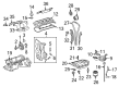
2003 Toyota Prius Timing Chain
Part Number: 13506-21050$209.11 MSRP: $298.55You Save: $89.44 (30%)Ships in 1-3 Business DaysProduct Specifications- Other Name: Chain Sub-Assembly, Timing; Chain Sub-Assembly
- Part Name Code: 13506
- Item Weight: 1.20 Pounds
- Item Dimensions: 6.3 x 3.3 x 1.2 inches
- Condition: New
- Fitment Type: Direct Replacement
- SKU: 13506-21050
- Warranty: This genuine part is guaranteed by Toyota's factory warranty.
2003 Toyota Prius Timing Chain
Looking for affordable OEM 2003 Toyota Prius Timing Chain? Explore our comprehensive catalogue of genuine 2003 Toyota Prius Timing Chain. All our parts are covered by the manufacturer's warranty. Plus, our straightforward return policy and speedy delivery service ensure an unparalleled shopping experience. We look forward to your visit!
2003 Toyota Prius Timing Chain Parts Q&A
- Q: How to remove and install the timing chain and related components on 2003 Toyota Prius?A: The first step entails disconnecting both the battery negative terminal as well as the HV battery service plug before uninstalling the outer front cowl top panel assembly together with the right-hand engine under cover. Engine coolant drainage should occur before you remove the air cleaner assembly through MAF meter connector detachment and EVAP hose disconnection and the loosening of two hose clamps and removal of three bolts. To remove the brake reservoir tank disconnect the brake fluid level sensor connector then remove the 2 bolts before suspension of the tank and completion of bracket removal using the 3 bolts. Unplug the ignition connectors along with all 4 injector connectors and both VSV connectors and disconnect the camshaft position sensor connector and the water temperature connector and camshaft timing oil control valve connector. Reach the air inlet engine coolant reservoir tank VSV from the engine mounting insulator and drive belt and right-hand engine mounting insulator by setting a jack under the engine with a wooden block while removing 5 bolts and 2 nuts. Finish the engine wire removal by undoing 3 cover bolts then completely remove the cylinder head cover through the process of dissociating ignition coils and extracting two PCV hoses and seven bolts, two seal washers, and two nuts. Set the No. 1 cylinder to TDC compression by rotating the crankshaft pulley until the timing mark indicates "0" and checks that the camshaft timing sprocket and valve timing controller assembly facing up. If marks do not align, rotate crankshaft one full revolution. Uninstall the crankshaft pulley with SST 09213-70011 and 09330-00021 and remove the crankshaft position sensor right-hand engine mounting bracket from four bolts, water pump, oil control valve, and timing chain cover by disconnecting 13 bolts alongside a nut then separate the cover by employing a torx wrench socket (E8) to eliminate the stud bolt while prying off the cover with care to prevent damage. Both O-rings from the cylinder block and oil pan No.1 must be removed before proceeding with the removal of the chain tensioner and chain tensioner slipper and finally the chain vibration damper. The inspection includes using vernier calipers to check 16 links of the timing chain length alongside sprocket diameters which must have maximum elongation under 123.2 mm (4.850 inch) while sprocket sizes stay within specifications. Check the chain tensioner slipper and vibration damper for wear because it should not surpass 1.0 mm (0.039 inch) while making sure the chain tensioner slides smoothly. The crankshaft front oil seal replacement starts with cutting the lip then extracting the seal with care using SST 09612-22011 to tap in the new component. Start crankshaft positioning at ATDC 40-140° then install the intake and exhaust sprocket at ATDC 20° before resetting the crankshaft to ATDC 20°. Add the chain vibration damper with 9.0 Nm (92 kgf-cm, 80 inch lbs.) torque on its two bolts. Align the match marks among the yellow timing chain mark plate and both camshaft and crankshaft timing sprockets. Install the chain tensioner slipper into position. To install the chain tensioner you should push in the plunger before rotating the lock plate upward while you insert a 2.5 mm (0.098 inch) bar into the lock plate holes and secure it with 2 bolts torqued to 9.0 Nm (92 kgf-cm, 80 inch lbs.). Verify the timing sprocket tension between the exhaust and intake camshaft timing components after you remove the 2.5mm clamp. The service requires attention to following steps: first clean the timing chain cover surfaces then the cylinder head and cylinder block surfaces before packing the timing chain cover with Part No. 08826-00100 or equivalent and installing it with new O-rings and water pump using 16 bolts and 3 nuts in multiple passing torque sequences. The right-hand engine mounting bracket requires seal packing Part No. 08826-00080 and 4 bolts applying 55 Nm (561 kgf-cm, 41 ft-lbs) torque before installing the crankshaft position sensor followed by the oil control valve at required torque values. Safely position the crankshaft pulley by setting its pin correctly while tightening it with SST 09213-70011 along with SST 09330-00021 at 128 Nm (1,300 kgf-cm, 94 ft. lbs.). The cylinder head cover must incorporate a new gasket together with two seal packing units (Part No. 08826-00080 or equivalent) that needs secure installation using seven bolts, two seal washers, and two nuts at 10 Nm (100 kgf-cm, 7 ft. lbs.) before PCV hose attachment is completed. The right-hand engine mounting insulator gets installed by using 5 bolts and 2 nuts while connecting engine wires to the cylinder head cover then putting on the ignition coils. The VSV needs installation on right-hand engine mounting insulator followed by installation on drive belt, engine coolant reservoir tank, air inlet, then reconnecting all connectors. After the installation of main assemblies and engine coolant addition, the replacement technician must perform a road test of the system to verify correct operation and shift points, smooth functionality, absence of abnormal noises while also checking for shock slippage, followed by another coolant recheck.
Related 2003 Toyota Prius Parts
 2003 Toyota Prius Engine Mount
 2003 Toyota Prius Timing Cover
 2003 Toyota Prius Camshaft
 2003 Toyota Prius Cylinder Head
 2003 Toyota Prius Cylinder Head Gasket
 2003 Toyota Prius Dipstick
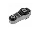 2003 Toyota Prius Engine Mount Torque Strut
 2003 Toyota Prius Exhaust Valve
 2003 Toyota Prius Harmonic Balancer
 2003 Toyota Prius Intake Valve
 2003 Toyota Prius Oil Pan
 2003 Toyota Prius Oil Pump Gasket