×
ToyotaParts- Hello
- Login or Register
- Quick Links
- Live Chat
- Track Order
- Parts Availability
- RMA
- Help Center
- Contact Us
- Shop for
- Toyota Parts
- Scion Parts
My Garage
My Account
Cart
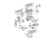
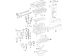
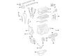
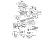
OEM Toyota Matrix Cylinder Head Gasket
Engine Cylinder Head Gasket- Select Vehicle by Model
- Select Vehicle by VIN
Select Vehicle by Model
orMake
Model
Year
Select Vehicle by VIN
For the most accurate results, select vehicle by your VIN (Vehicle Identification Number).
4 Cylinder Head Gaskets found


Toyota Matrix Head Gasket Part Number: 11115-28040
$74.52 MSRP: $104.61You Save: $30.09 (29%)Ships in 1-3 Business Days


Toyota Matrix Head Gasket Part Number: 11115-22050
$64.45 MSRP: $90.47You Save: $26.02 (29%)Ships in 1 Business Day
Toyota Matrix Head Gasket Part Number: 11115-37062
$67.41 MSRP: $94.63You Save: $27.22 (29%)Ships in 1-2 Business Days
Toyota Matrix Head Gasket Part Number: 11115-22060
$59.14 MSRP: $82.32You Save: $23.18 (29%)
Toyota Matrix Cylinder Head Gasket
Choose genuine Cylinder Head Gasket that pass strict quality control tests. You can trust the top quality and lasting durability. Shopping for OEM Cylinder Head Gasket for your Toyota Matrix? Our website is your one-stop destination. We stock an extensive selection of genuine Toyota Matrix parts. The price is affordable so you can save more. It only takes minutes to browse and find the exact fit. Easily add to cart and check out fast. Our hassle-free return policy will keep you stress-free. We process orders quickly for swift delivery. Your parts will arrive faster, so you can get back on the road sooner.
Toyota Matrix Cylinder Head Gasket is one of the most recommended products because of its durability and efficiency in the Matrix series; the first and second generations were manufactured from 2002 to 2013. This essential part is to prevent leakage of combustion products, coolant, and oil which is very vital in the enhancement of excellent functioning as well as ensuring that the engine will not overheat. The Toyota Matrix generally employs optimal in class and robust Multi Layer Steel MLS gaskets for the Cylinder Head Gasket so that it can sustain the day to day use and stress. Defective Cylinder Head Gasket may be referred as "blown head gasket" may cause severe damage in the engine which may show symptoms like coolant or oil leakage, white smoke coming from the exhaust or a sign of overheating engine. For one to save on the expenses of repairing the Toyota Matrix Cylinder Head Gasket, it is wise to have it serviced over a given period, which will be of help in the longevity of the engine part. This component plays an important role in the functionality of the car and in addition to this it improves on the general performance and safety of the vehicle hence making it a great feature in the market. Therefore, the Cylinder Head Gasket for Toyota Matrix that fits different models is a good exhibit of Toyota's dedication to quality and performance, thus making it a popular option for drivers who need to be assured on the roads.
Toyota Matrix Cylinder Head Gasket Parts and Q&A
- Q: How to remove the cylinder head gasket on Toyota Matrix?A:A proper procedure to remove the cylinder head gasket of the 2AZ-FE engine begins with fuel system pressure discharge followed by battery cable disconnect from the negative terminal then removal of the front wiper arm head cap together with the left and right front wiper arm and blade assemblies. The hood to cowl top seal should be removed together with the right and left cowl top ventilator louvers and the windshield Wiper Motor and link assembly. The worker should detach the outer cowl top panel followed by the suspension tower damper assembly (only if the front strut bar is present) before removing the right front wheel. The engineer needs to remove engine under covers from both sides and drain motor oil and engine coolant from the No. 1 engine cover sub-assembly. The repair technician should detach the center Exhaust Pipe assembly for both 2WD and 4WD vehicles together with the front exhaust pipe assembly, V-ribbed belt and generator assembly. The radiator reserve tank assembly can be separated before removing the air cleaner cap sub-assembly with hose and the Throttle Body assembly and Ignition Coil assembly and Spark Plug. Proceed by removing the cylinder head cover sub-assembly before disconnecting the fuel main tube and then taking off the fuel delivery pipe sub-assembly. The technician must take away the Camshaft timing oil control valve assembly together with the Intake Manifold and the No. 1 intake manifold insulator as well as the manifold stays and the No. 1 exhaust manifold heat insulator. Disconnection of the air-fuel ratio sensor connector followed by 5 nut removal allows separation of the exhaust manifold converter sub-assembly. The right side engine mounting insulator sub-assembly can be removed under support of an engine floor jack. The replacement process starts with removing the idler pulley sub-assembly followed by the oil pan sub-assembly using new bolts to install the No. 1 and No. 2 engine hangers under sling device control while careful sealing sealer cutting procedures must be observed. Set the No. 1 cylinder to TDC/compression by appropriate timing of the crankshaft pulley timing mark with the timing chain cover while also checking the camshaft timing gear and sprocket alignment. First remove the crankshaft pulley then proceed to eliminate the No. 1 chain tensioner assembly, V-ribbed belt tensioner assembly, Crankshaft Position Sensor and timing chain or belt cover sub-assembly from the system. Extraction of the No. 1 crankshaft position sensor plate along with timing chain guide and chain tensioner slipper and No. 1 chain vibration damper must occur. The crankshaft timing gear or sprocket and chain sub-assembly need to be detached together after which you should remove the No. 2 chain sub-assembly by aligning the adjusting hole through crankshaft rotation followed by gear locking. The service procedure starts with disconnecting No. 1 radiator hose and margin and inlet heater water hoses followed by the engine wire separation by disconnecting multiple connectors while untying the ground cable. It is time to remove the cylinder head sub-assembly together with the No. 2 camshaft, camshaft, No. 1 and No. 2 camshaft bearings using a uniform tightening pattern of 10 cylinder head bolts and plate washers while following a specific sequence. Afterward, carefully remove the cylinder head from the contact surfaces and take off the cylinder head gasket.
- Q: How to install the cylinder head gasket on Toyota Matrix?A:A new gasket installation for the 2AZ-FE engine consists of setting the gasket on the block surface where the Lot No. stamp points upward followed by oil removal from contact areas while watching installation alignment. Install the cylinder head on the gasket before applying light engine oil to the threads and under heads of cylinder head set bolts. Use a 10 mm bi-hexagon wrench to evenly tighten 10 bolts and plate washers to 70 Nm (714 kgf-cm, 52 ft-lbf). Paint the front part of the bolts then increase additional torque to 90 degrees until the paint marks show a 90-degree relationship with the bolt fronts. After installing the No. 1 and No. 2 Camshaft bearings it is necessary to fit the camshafts before securing all hoses including inlet and outlet heater water and the No. 1 radiator hose. The ground cable of the engine wire must be torqued to 8.4 Nm (86 kgf-cm, 74 in-lbf) while all relevant sensors get connected. The No. 2 chain sub-assembly installation requires the crankshaft key placement then the alignment of yellow mark links at timing marks before tightening the oil pump drive shaft sprocket to 30 Nm (301 kgf-cm, 22 ft-lbf). Proper alignment of timing marks is necessary while installing the crankshaft timing gear or sprocket and the No. 1 chain vibration damper with a torque of 9.0 Nm (92 kgf-cm, 80 in-lbf) and the chain sub-assembly. After installing the chain tensioner slipper and timing chain guide the service technician must position the No. 1 Crankshaft Position Sensor plate. The installation of the timing chain or belt cover sub-assembly requires the additional step of the No. 1 chain tensioner assembly followed by the V-ribbed belt tensioner assembly which all need to be installed using the stated torque requirements. Place the crankshaft pulley under the restraint of Special Service Tool: 09213-54015 91651-60855 while applying 180 Nm (1835 kgf-cm, 133 ft-lbf) of torque. Subsequently install the oil pan sub-assembly with seal packing and tighten its bolts and nuts to 9.0 Nm (92 kgf-cm, 80 in-lbf). The crankshaft position sensor with specified torque values should be installed together with the idler pulley sub-assembly as well as the engine mounting insulator sub-assembly RH. The exhaust manifold converter sub-assembly needs a new gasket and its nuts must be tightened to 37 Nm (377 kgf-cm, 27 ft-lbf). Proceed with component installation that includes Intake Manifold followed by camshaft timing oil control valve assembly and fuel delivery pipe sub-assembly and engine oil level dipstick guide while maintaining proper torque standards. To complete the repair you should put on the V-ribbed belt before installing the front Exhaust Pipe assembly, the center exhaust pipe assembly and reconnecting the negative battery terminal at 5.4 Nm (55 kgf-cm, 48 in-lbf). Next, add engine oil and coolant then inspect the system for leaks.


Related Toyota Matrix Parts
 Toyota Matrix Timing Chain
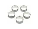 Toyota Matrix Camshaft Bearing
 Toyota Matrix Crankshaft Pulley
 Toyota Matrix Cylinder Head
 Toyota Matrix Dipstick
 Toyota Matrix Dipstick Tube
 Toyota Matrix Harmonic Balancer
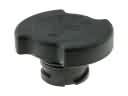 Toyota Matrix Oil Filler Cap
 Toyota Matrix Oil Pump Gasket
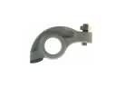 Toyota Matrix Rocker Arm
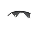 Toyota Matrix Timing Chain Guide
 Toyota Matrix Timing Cover