×
ToyotaParts- Hello
- Login or Register
- Quick Links
- Live Chat
- Track Order
- Parts Availability
- RMA
- Help Center
- Contact Us
- Shop for
- Toyota Parts
- Scion Parts
My Garage
My Account
Cart
OEM Scion tC Control Arm
Suspension Arm- Select Vehicle by Model
- Select Vehicle by VIN
Select Vehicle by Model
orMake
Model
Year
Select Vehicle by VIN
For the most accurate results, select vehicle by your VIN (Vehicle Identification Number).
5 Control Arms found


Scion tC Arm Sub-Assembly, Front Suspension, Lower Driver Side Part Number: 48069-12300
$173.54 MSRP: $245.66You Save: $72.12 (30%)Ships in 1-3 Business Days

Scion tC Track Bar, Driver Side Part Number: 48730-21110
$152.27 MSRP: $215.55You Save: $63.28 (30%)Ships in 1-3 Business Days

Scion tC Lower Control Arm, Passenger Side Part Number: 48068-12300
$163.90 MSRP: $232.02You Save: $68.12 (30%)Ships in 1-3 Business Days

Scion tC Lower Control Arm, Driver Side Part Number: 48069-21020
$178.85 MSRP: $255.36You Save: $76.51 (30%)Ships in 1-3 Business DaysScion tC Lower Control Arm, Passenger Side Part Number: 48068-21020
$225.88 MSRP: $322.51You Save: $96.63 (30%)Ships in 1-3 Business Days
Scion tC Control Arm
Choose genuine Control Arm that pass strict quality control tests. You can trust the top quality and lasting durability. Shopping for OEM Control Arm for your Scion tC? Our website is your one-stop destination. We stock an extensive selection of genuine Scion tC parts. The price is affordable so you can save more. It only takes minutes to browse and find the exact fit. Easily add to cart and check out fast. Our hassle-free return policy will keep you stress-free. We process orders quickly for swift delivery. Your parts will arrive faster, so you can get back on the road sooner.
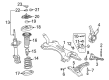
A control arm is one of the components that constitute an automobile suspension system, and the Scion tC Control Arm is no exception since it's a reputable part of the Scion tC vehicle. The control arm is located directly between the front wheel assemblies and the frame of the vehicle, and it is responsible for controlling the radial movements of the wheel, which increases the vehicle's efficiency as well as safety. Suitable for different Scion tC models, the Control Arm can be installed as lower or upper links according to the type of the suspension; with MacPherson strut configuration using track control arms quite often. This flexibility helps the Scion tC to keep a proper get a handle on and balance making it ideal for enthusiasts. The Control Arm's structure is commonly in the form of a triangular wishbone and allows the car to be more stable while offering vast control without employing extra links, which cemented its standing in the automotive industry. Such indications as rumbles or excessive swaying of the wheels are important in preventing damage to Scion tC's suspension. The Scion tC has been one of the recent and successful models most known for its plan price range and sporty look. In light with this, the Scion tC Control Arm is one of the critical components that contribute to the enhancement of the tC's stability and comfort which in effect makes it a component that is essential part of this remarkable car.
Scion tC Control Arm Parts and Q&A
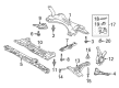
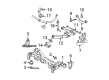
- Q: How to install the Control Arm in the rear suspension No. 1 arm assembly on Scion tC?A:The procedure for rear suspension No. 1 arm assembly installation starts with suspension support stopper and suspension arm bracket LH installation followed by nut temporary tightening. For installation of the rear side suspension No. 1 arm LH you should temporarily tighten both the bolt and nut when holding the nut in position during bolt installation. Ordinarily tighten 3 fasteners to a torque value of 65 Nm (663 kgf-cm, 48 ft-lbf). Begin by attaching the front side rear axle carrier LH to the suspension No. 1 arm LH while loosely tightening the nut. Then install the axle carrier LH onto No. 1 suspension arm LH and loosely fasten both the bolt and nut. Secure the Shock Absorber with coil spring on the suspension No. 1 arm LH after temporarily tightening both the bolt and nut. The first step involves attaching the lower control arm LH through its bolt then securing it but without full tightening to the axle carrier LH using a spare nut. Secure the rear disc brake caliper assembly followed by the rear stabilizer link assembly while using a 5 mm hexagon wrench for any ball joint rotation during stabilizer link LH nut tightening to 44 Nm (449 kgf-cm, 32 ft-lbf). Fasten the skid control sensor wire using a bolt which needs tightening to 5.0 Nm torque before connecting the skid control sensor wire. Fasten the No. 3 Parking Brake Cable via two bolts achieving 6.0 Nm (61 kgf-cm, 53 in-lbf) torque for each one, then install the rear wheel applying 103 Nm (1,050 kgf-cm, 76 ft-lbf) torque. Bounce the vehicle to stabilize suspension followed by full bolt tightening on the rear suspension No. 1 arm assembly during which the vehicle should be empty with the nut set to 110 Nm (1,120 kgf-cm, 81 ft-lbf) and the bolt set to 115 Nm (1,170 kgf-cm, 85 ft-lbf) and the bolt and nut set to 140 Nm (1,430 kgf-cm, 103 ft-lbf) while holding the nut in place during bolt installation. The installation process requires tightening the nut to 105 Nm (1,070 kgf-cm, 77 ft-lbf) before inserting the clip from the vehicle's front side. For proper alignment the holes of the clip should be adjusted by tightening the nut while keeping the tightening angle below 60 degrees. Prior to finishing the bolt and nut installation fully tighten the hardware to 74 Nm (755 kgf-cm, 55 ft-lbf) by maintaining constant pressure on the nut. The lower control arm assembly requires tightening the nut to 105 Nm (1,070 kgf-cm, 77 ft-lbf) followed by clip installation while aligning holes as needed before inserting the clip from behind the vehicle. Last, bolt tightening to 115 Nm (1,170 kgf-cm, 85 ft-lbf) is necessary. The last stage of inspection includes both alignment adjustments of rear wheels and ABS speed sensor signal testing.
- Q: How to remove the Control Arm from the rear suspension No. 1 assembly on Scion tC?A:A vehicle technician should start by taking off the rear wheel before proceeding with the removal of the rear suspension No. 1 arm assembly. The complete process of removing the No. 3 Parking Brake Cable assembly involves taking out two bolts followed by disconnecting its cable. A successful connectivity separation occurs through both steps involving the removal of the bolt from the sensor wire connector. The rear stabilizer link assembly needs disposal when workers detach the stabilizer link LH and eliminate the nut while using a 5mm hexagon wrench to retain the stud if it rotates with the nut. Support the No. 1 suspension arm LH by removing the bolt to separate the member side lower control arm LH from the rear suspension member. Remove the clip and the nut as well. Use Special Service Tool: 09610-20012 to take off the lower control arm LH from the axle carrier LH while safeguarding the dust cover from damage. The rear automotive assembly necessitates disc brake caliper removal before removing its corresponding disc. Detach the clip and nut before using Special Service Tool: 09628-62011 to disconnect the axle carrier LH front side from the No. 1 suspension arm LH. Afterward, hang the upper control arm onto the axle carrier LH side by using a wire or equivalent. Disconnect the suspension No. 1 arm LH from the axle carrier LH side by first removing its bolt then its nut while maintaining the nut in place. The same steps should be followed to disconnect the Shock Absorber with coil spring and the rear side suspension No. 1 arm LH but maintain hold of the nut until bolt removal. The suspension No. 1 arm LH requires the 3 bolt removal before you can detach the nut followed by the suspension arm bracket LH and suspension support stopper.


Related Scion tC Parts
 Scion tC Ball Joint
 Scion tC Shock Absorber
 Scion tC Sway Bars
 Scion tC Camber and Alignment Kit
 Scion tC Control Arm Bracket
 Scion tC Crossmember Bushing
 Scion tC Front Cross-Member
 Scion tC Shock and Strut Boot
 Scion tC Steering Knuckle
 Scion tC Strut Mounts
 Scion tC Suspension Strut Rod
 Scion tC Sway Bar Link
Browse Scion tC Control Arm by Years
2016
2015
2014
2013
2012
2011
2010
2009
2008
2007
2006
2005