×
ToyotaParts- Hello
- Login or Register
- Quick Links
- Live Chat
- Track Order
- Parts Availability
- RMA
- Help Center
- Contact Us
- Shop for
- Toyota Parts
- Scion Parts
My Garage
My Account
Cart
OEM 2006 Scion tC Control Arm
Suspension Arm- Select Vehicle by Model
- Select Vehicle by VIN
Select Vehicle by Model
orMake
Model
Year
Select Vehicle by VIN
For the most accurate results, select vehicle by your VIN (Vehicle Identification Number).
3 Control Arms found


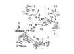
2006 Scion tC Track Bar, Driver Side
Part Number: 48730-21110$152.27 MSRP: $215.55You Save: $63.28 (30%)Ships in 1-3 Business DaysProduct Specifications- Other Name: Arm Assembly, Lower Control; Suspension Track Bar, Rear Left; Trailing Arm; Arm Assembly, Lower Control, Driver Side
- Position: Driver Side
- Part Name Code: 48730
- Item Weight: 3.10 Pounds
- Item Dimensions: 18.9 x 6.8 x 3.7 inches
- Condition: New
- Fitment Type: Direct Replacement
- SKU: 48730-21110
- Warranty: This genuine part is guaranteed by Toyota's factory warranty.


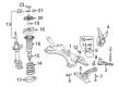
2006 Scion tC Lower Control Arm, Driver Side
Part Number: 48069-21020$178.85 MSRP: $255.36You Save: $76.51 (30%)Ships in 1-3 Business DaysProduct Specifications- Other Name: Arm Sub-Assembly, Suspension; Suspension Control Arm, Front Left; Control Arm Assembly; Arm Sub-Assembly, Front Suspension, Lower Driver Side; Control Arm
- Position: Lower Driver Side
- Part Name Code: 48069
- Item Weight: 1.70 Pounds
- Item Dimensions: 20.9 x 4.0 x 19.3 inches
- Condition: New
- Fitment Type: Direct Replacement
- SKU: 48069-21020
- Warranty: This genuine part is guaranteed by Toyota's factory warranty.
2006 Scion tC Lower Control Arm, Passenger Side
Part Number: 48068-21020$219.24 MSRP: $313.02You Save: $93.78 (30%)Ships in 1-3 Business DaysProduct Specifications- Other Name: Arm Sub-Assembly, Suspension; Suspension Control Arm, Front Right; Control Arm Assembly; Arm Sub-Assembly, Front Suspension, Lower Passenger Side; Control Arm
- Position: Passenger Side
- Part Name Code: 48068
- Item Weight: 1.70 Pounds
- Item Dimensions: 20.3 x 4.0 x 19.7 inches
- Condition: New
- Fitment Type: Direct Replacement
- SKU: 48068-21020
- Warranty: This genuine part is guaranteed by Toyota's factory warranty.
2006 Scion tC Control Arm
Looking for affordable OEM 2006 Scion tC Control Arm? Explore our comprehensive catalogue of genuine 2006 Scion tC Control Arm. All our parts are covered by the manufacturer's warranty. Plus, our straightforward return policy and speedy delivery service ensure an unparalleled shopping experience. We look forward to your visit!
2006 Scion tC Control Arm Parts Q&A
- Q: How to service and repair the Control Arm in the rear suspension on 2006 Scion tC?A: Service and repair of the rear suspension No. 1 arm requires removing the rear wheel while disconnecting the No. 3 parking brake cable assembly through the removal of its 2 bolts. Before proceeding with the skid control sensor wire disconnect you need to first remove the bolt securing the wire then disconnect its connector. Start by uncovering the rear stabilizer link assembly with its nut loose. When the ball joint rotates with this loosened nut perform a stable holding with a 5 mm hexagon wrench on the stud. To separate the lower control arm from the rear suspension member support the No. 1 suspension arm LH first then remove its bolt and conclude by removing the clip and nut. The lower control arm LH can be extracted from the axle carrier LH using Special Service Tool: 09610-20012 while safeguarding the dust cover from damage. Disconnect the rear disc brake caliper assembly and rear disc and rear suspension No. 1 arm assembly by removing the clip and nut. After that disconnect the axle carrier LH front side from the No. 1 suspension arm LH using Special Service Tool: 09628-62011 while focusing on not damaging the dust cover. Use a wire to suspend the upper control arm on the axle carrier LH while removing the bolt and nut which disconnects the suspension No. 1 arm LH from the axle carrier LH side. Proceed by disconnecting the shock absorber with coil spring and finally remove the rear side suspension No. 1 arm LH. The installation requires removal of three bolts and accompanying hardware such as the suspension No. 1 arm LH with its nut along with the suspension arm bracket LH but excluding the suspension support stopper. Start by mounting the suspension support stopper with suspension arm bracket LH which requires temporary nut tightening followed by connecting and temporarily securing the rear side suspension No. 1 arm LH with its bolt and nut. Fixedly attach the front side rear axle carrier LH to the suspension No. 1 arm LH while loosely tightening the existing nut. Then install 3 bolts and torque them at 65 Nm (663 kgf-cm, 48 ft. lbs.). Move forward by attaching the axle carrier LH to the No. 1 suspension arm LH, shock absorber with coil spring, then temporarily secure bolts and nuts. You must first install the lower control arm LH while tightening the bolt only before connecting it to the axle carrier LH while tightening the nut. Screw in both the rear disc along with the rear disc brake caliper assembly. The stabilizer link LH part requires installation with its nut before torquing to 44 Nm (449 kgf-cm, 32 ft. lbs.). Toggle the skid control sensor wire by using a bolt which should be torqued to 5.0 Nm (51 kgf-cm, 44 inch lbs.) before attaching the sensor connector. The installation of the No. 3 parking brake cable assembly requires connecting it with its 2 bolts along with 6.0 Nm (61 kgf-cm, 53 inch lbs.) torquing then installing the rear wheel with 103 Nm (1,050 kgf-cm, 76 ft. lbs.). A suspension stabilizing process must occur first by bouncing the vehicle several times followed by complete assembly tightening of the rear suspension No. 1 arm assembly while emptying the vehicle and securing the nut to 110 Nm (1,120 kgf-cm, 81 ft. lbs.) and the bolt to 115 Nm (1,170 kgf-cm, 85 ft. lbs.) and the bolt and nut to 140 Nm (1,430 kgf-cm, 103 ft. lbs.) while maintaining nut position. Final assembly torques should be 105 Nm (1,070 kgf-c The first step includes installing the clip while adjusting the holes for proper alignment then fully tightening the nut to 105 Nm (1,070 kgf-cm, 77 ft. lbs.). First, fully tighten the bolt and nut combination which requires 74 Nm (755 kgf-cm, 55 ft. lbs.) torque because the nut should remain in position. Then tighten the lower control arm assembly by turning the nut to 105 Nm (1,070 kgf-cm, 77 ft. lbs.) then follow with bolt tightening at 115 Nm (1,170 kgf-cm, 85 ft. lbs.). The technician should inspect the rear wheel alignment together with checking the ABS speed sensor signal.
Related 2006 Scion tC Parts
 2006 Scion tC Ball Joint
 2006 Scion tC Coil Springs
 2006 Scion tC Shock Absorber
 2006 Scion tC Alignment Bolt
 2006 Scion tC Control Arm Bolt
 2006 Scion tC Control Arm Bracket
 2006 Scion tC Crossmember Bushing
 2006 Scion tC Front Cross-Member
 2006 Scion tC Shock And Strut Mount
 2006 Scion tC Suspension Strut Rod
 2006 Scion tC Sway Bar Bracket
 2006 Scion tC Sway Bar Link