×
ToyotaParts- Hello
- Login or Register
- Quick Links
- Live Chat
- Track Order
- Parts Availability
- RMA
- Help Center
- Contact Us
- Shop for
- Toyota Parts
- Scion Parts
My Garage
My Account
Cart
OEM 2010 Scion tC Control Arm
Suspension Arm- Select Vehicle by Model
- Select Vehicle by VIN
Select Vehicle by Model
orMake
Model
Year
Select Vehicle by VIN
For the most accurate results, select vehicle by your VIN (Vehicle Identification Number).
3 Control Arms found


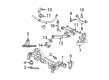
2010 Scion tC Track Bar, Driver Side
Part Number: 48730-21110$152.27 MSRP: $215.55You Save: $63.28 (30%)Ships in 1-3 Business DaysProduct Specifications- Other Name: Arm Assembly, Lower Control; Suspension Track Bar, Rear Left; Trailing Arm; Arm Assembly, Lower Control, Driver Side
- Position: Driver Side
- Part Name Code: 48730
- Item Weight: 3.10 Pounds
- Item Dimensions: 18.9 x 6.8 x 3.7 inches
- Condition: New
- Fitment Type: Direct Replacement
- SKU: 48730-21110
- Warranty: This genuine part is guaranteed by Toyota's factory warranty.


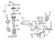
2010 Scion tC Lower Control Arm, Driver Side
Part Number: 48069-21020$178.85 MSRP: $255.36You Save: $76.51 (30%)Ships in 1-3 Business DaysProduct Specifications- Other Name: Arm Sub-Assembly, Suspension; Suspension Control Arm, Front Left; Control Arm Assembly; Arm Sub-Assembly, Front Suspension, Lower Driver Side; Control Arm
- Position: Lower Driver Side
- Part Name Code: 48069
- Item Weight: 1.70 Pounds
- Item Dimensions: 20.9 x 4.0 x 19.3 inches
- Condition: New
- Fitment Type: Direct Replacement
- SKU: 48069-21020
- Warranty: This genuine part is guaranteed by Toyota's factory warranty.
2010 Scion tC Lower Control Arm, Passenger Side
Part Number: 48068-21020$219.24 MSRP: $313.02You Save: $93.78 (30%)Ships in 1-3 Business DaysProduct Specifications- Other Name: Arm Sub-Assembly, Suspension; Suspension Control Arm, Front Right; Control Arm Assembly; Arm Sub-Assembly, Front Suspension, Lower Passenger Side; Control Arm
- Position: Passenger Side
- Part Name Code: 48068
- Item Weight: 1.70 Pounds
- Item Dimensions: 20.3 x 4.0 x 19.7 inches
- Condition: New
- Fitment Type: Direct Replacement
- SKU: 48068-21020
- Warranty: This genuine part is guaranteed by Toyota's factory warranty.
2010 Scion tC Control Arm
Looking for affordable OEM 2010 Scion tC Control Arm? Explore our comprehensive catalogue of genuine 2010 Scion tC Control Arm. All our parts are covered by the manufacturer's warranty. Plus, our straightforward return policy and speedy delivery service ensure an unparalleled shopping experience. We look forward to your visit!
2010 Scion tC Control Arm Parts Q&A
- Q: How to install the front lower Control Arm on 2010 Scion tC?A: The installation of the front lower suspension arm starts with securing the No. 1 suspension lower arm LH to the suspension crossmember through temporary 2-bolt and nut fastening. The front suspension crossmember sub-assembly installation should be your next step followed by fitting the No. 1 hook. Screw in a bolt on the No. 1 suspension lower arm LH to attach it with lower ball joint using 2 nuts then apply torque at 89 Nm (908 kgf-cm, 66 ft-lbf). A double application of the identical setup should occur on the RH side too. You must tighten the front stabilizer link assembly LH to the shock absorber through a nut with 74 Nm torque (755 kgf-cm, 55 ft-lbf). Hold the stud with a 6 mm hexagon wrench when performing this operation if needed. After assembling the RH components perform the same process for the opposite side. Connect the pressure feed tube assembly while also installing the tie rod end sub-assemblies LH and RH and center exhaust pipe assembly and front floor panel brace. The suspension needs stabilization by tightening the front tire to 103 Nm (1,050 kgf-cm, 76 ft-lbf) torque before dropping the vehicle for multiple bouncing motions. Use a 4 post lift to secure the tire condition touching the ground before tightening both bolts on the No. 1 suspension lower arm LH to 137 Nm (1,400 kgf-cm, 101 ft-lbf) while preventing the nut from rotating during rear side bolt torque. Install the steering column hole cover sub-assembly and the steering intermediate shaft assembly together before adding the column hole cover silencer sheet and engine cover sub-assembly number 1. Power steering fluid must be added and the power steering fluid needs bleeding then check the reservoir and search for any fluid leaks. The final process involves installing the hood sub-assembly followed by performing front wheel alignment checks and installing both engine under covers towards the left and right sides.
Related 2010 Scion tC Parts
 2010 Scion tC Ball Joint
 2010 Scion tC Coil Springs
 2010 Scion tC Shock Absorber
 2010 Scion tC Alignment Bolt
 2010 Scion tC Control Arm Bolt
 2010 Scion tC Control Arm Bracket
 2010 Scion tC Crossmember Bushing
 2010 Scion tC Front Cross-Member
 2010 Scion tC Shock And Strut Mount
 2010 Scion tC Suspension Strut Rod
 2010 Scion tC Sway Bar Bracket
 2010 Scion tC Sway Bar Link