×
ToyotaParts- Hello
- Login or Register
- Quick Links
- Live Chat
- Track Order
- Parts Availability
- RMA
- Help Center
- Contact Us
- Shop for
- Toyota Parts
- Scion Parts
My Garage
My Account
Cart
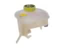
OEM Scion tC Parking Brake Cable
Emergency Parking Brake Release Cable- Select Vehicle by Model
- Select Vehicle by VIN
Select Vehicle by Model
orMake
Model
Year
Select Vehicle by VIN
For the most accurate results, select vehicle by your VIN (Vehicle Identification Number).
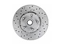
5 Parking Brake Cables found


Scion tC Front Cable Part Number: 46410-21040
$27.23 MSRP: $37.91You Save: $10.68 (29%)Ships in 1-3 Business Days
Scion tC Rear Cable Part Number: 46420-21090
$71.92 MSRP: $100.95You Save: $29.03 (29%)Ships in 1-3 Business Days
Scion tC Rear Cable Part Number: 46430-21120
$73.22 MSRP: $102.78You Save: $29.56 (29%)
Scion tC Cable Part Number: 46420-21110
$88.03 MSRP: $123.57You Save: $35.54 (29%)Ships in 1-3 Business Days
Scion tC Cable Part Number: 46430-21110
$94.55 MSRP: $132.72You Save: $38.17 (29%)
Scion tC Parking Brake Cable
Choose genuine Parking Brake Cable that pass strict quality control tests. You can trust the top quality and lasting durability. Shopping for OEM Parking Brake Cable for your Scion tC? Our website is your one-stop destination. We stock an extensive selection of genuine Scion tC parts. The price is affordable so you can save more. It only takes minutes to browse and find the exact fit. Easily add to cart and check out fast. Our hassle-free return policy will keep you stress-free. We process orders quickly for swift delivery. Your parts will arrive faster, so you can get back on the road sooner.
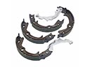
Parking Brake Cable is another important system in Scion tC for parking brake, so the Scion tC will not roll away especially when parked on the inclined place. This is a basic cable that links the parking brake to the other braking systems to provide a boost in operational effectiveness and safety from chances of unwanted movement of the car. When it comes to the Parking Brake Cable, users marvel at the product's ability to perform at optimal levels, and it has to be be said that the product is quite durable, proving quite helpful to owners of Scion tC cars. Compatibility with the different types of tC models helps the driver to retain the optimal performance irrespective of the year and trim of the car. Another requirement of the Scion tC is the proper servicing of the Parking Brake Cable since a faulty Parking Brake can be fatal due to the inability of the Scion tC to adequately set the parking brake. They are inability to engage the parking brake and the engagement light comes on which is a sign for a cable check. The Scion tC, a compact cars launched for affordable sporty cars have been accepted by young drivers, and therefore there should be enhanced component like Parking Brake Cable. Notable characteristics of the Parking Brake Cable include durability in the material and construction of the product which is due to daily use. In general, Parking Brake Cable is an essential part of upgrading driving experience as well as safety for all the Scion tC aficionados.
Scion tC Parking Brake Cable Parts and Q&A
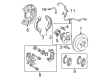
- Q: How to remove the parking brake cable on Scion tC?A:One should start cable removal by disconnecting it from the negative terminal and waiting 90 seconds to avoid Air Bag and seat belt pretensioner commands. The removal of the No. 2 parking brake cable requires the same method as the No. 3 cable procedure. You must begin by taking out the shift lever knob sub-assembly which goes with manual transaxle while following it with front upper console panel sub-assembly, rear upper console panel sub-assembly and finally the rear console box sub-assembly. Proceed to take off the parking brake lever sub-assembly together with front door scuff plate RH and cowl side trim sub-assembly RH. First remove the assembly of front seat RH and center Exhaust Pipe and parking brake cable heat insulator by unscrewing the two nuts. The No. 1 parking brake cable assembly needs disconnection from the parking brake equalizer and then a floor carpet should be turned back before removing the 2 bolts that secure the parking brake cable. Remove the rear wheel and proceed to take off the rear brake cylinder mounting LH assembly with its rear disc brake cylinder and its rear disc. Proceed to eliminate the parking brake shoe strut LH along with the parking brake shoe adjusting screw set and parking brake shoe assembly LH and parking brake shoe lever LH. The first procedure involves disconnecting the No. 3 parking brake cable assembly through the removal of its bolt and then unfastening it from the backing plate followed by removing the No. 1 fuel tank protector by unthreading its 5 bolts. Finally, the No. 3 parking brake cable assembly disconnects by removing the 4 bolts and body cable retainer before disconnecting from the parking brake equalizer and removing the cable.
- Q: How to install the No. 3 parking brake cable assembly and related components on Scion tC?A:The installation of the No. 3 parking brake cable assembly requires connecting the parking brake cable to the parking brake cable equalizer and securing it with 4 bolts while torquing bolt A to 6.0 Nm (61 kgf-cm, 53 in-lbf) and bolt B to 5.4 Nm (55 kgf-cm, 48 in-lbf). Use five bolts to secure the No. 1 fuel tank protector while torquing them to 5.4 Nm (55 kgf-cm, 48 in-lbf). The No. 3 parking brake cable assembly needs a bolt connection to the backing plate with torque setting at 8.0 Nm (82 kgf-cm, 71 in-lbf). The procedure requires parking brake shoe lever LH and assembly LH installation with adjusting screw set and parking brake shoe strut LH before application of high-temperature grease. Position the rear disc brake cylinder assembly LH on the mounting point of the rear disc along with the rear disc brake cylinder mounting LH. Tore the parking brake shoe clearance before attaching the rear wheel by torquing it to 103 Nm (1,050 kgf-cm, 76 ft-lbf). Fasten the No. 1 parking brake cable assembly to the parking brake equalizer with 2 bolts at 12.5 Nm (128 kgf-cm, 9 ft-lbf). Afterward, put on the floor carpet and complete the parking brake cable connection to the equalizer. Connect the parking brake cable heat insulator with 2 nuts before torquing them to 5.4 Nm (55 kgf-cm, 48 in-lbf). The assembly work includes installing the center Exhaust Pipe assembly together with the parking brake lever sub-assembly, front seat assembly RH, the cowl side trim sub-assembly RH, front door scuff plate RH, and rear console box assembly followed by rear upper console panel sub-assembly and front upper console panel sub-assembly and shift lever knob sub-assembly (for Manual Transaxle). The cable should be connected to the negative battery terminal while paying attention to potential post-reconnect initialization requirements. Perform a test of the ABS sensor signal followed by parking brake shoe and disc settlement before checking and adjusting the parking brake lever motion and inspecting for exhaust gas leakages.