×
ToyotaParts- Hello
- Login or Register
- Quick Links
- Live Chat
- Track Order
- Parts Availability
- RMA
- Help Center
- Contact Us
- Shop for
- Toyota Parts
- Scion Parts
My Garage
My Account
Cart
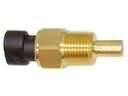
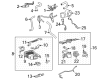
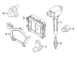
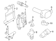
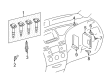
OEM Scion Knock Sensor
Engine Knock Sensor- Select Vehicle by Model
- Select Vehicle by VIN
Select Vehicle by Model
orMake
Model
Year
Select Vehicle by VIN
For the most accurate results, select vehicle by your VIN (Vehicle Identification Number).
4 Knock Sensors found


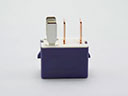
Scion Knock Sensor Part Number: 89615-06010
$142.28 MSRP: $201.42You Save: $59.14 (30%)Ships in 1-3 Business DaysProduct Specifications- Other Name: Sensor, Knock Control; Ignition Knock (Detonation) Sensor
- Replaces: 89615-BZ030, 89615-20090, 89615-BZ040

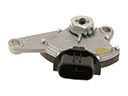
Scion Knock Sensor Part Number: 89615-WB001
$81.61 MSRP: $114.56You Save: $32.95 (29%)Ships in 1-3 Business DaysProduct Specifications- Other Name: Sensor, Knock Control; Ignition Knock (Detonation) Sensor

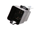
Scion Knock Sensor Part Number: SU003-06707
$61.47 MSRP: $80.25You Save: $18.78 (24%)Ships in 1-2 Business DaysProduct Specifications- Other Name: Sensor Assembly-Knock; Ignition Knock (Detonation) Sensor; Sensor, Knock Control
- Replaces: SU003-00415

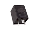
Scion Knock Sensor Part Number: 89615-52030
$144.75 MSRP: $204.91You Save: $60.16 (30%)Product Specifications- Other Name: Sensor, Knock Control; Ignition Knock (Detonation) Sensor
- Manufacturer Note: DENSO
- Replaces: 89615-52040
Scion Knock Sensor
OEM parts deliver unmatched quality you can rely on. They pass extensive quality control inspections. Scion produces them to the official factory specifications. This process helps prevent defects and imperfections. So you can get exceptional lifespan and a flawless fit. Need new OEM Scion Knock Sensor? You'll love our wide selection of genuine options. Shop in minutes and skip the hunt. Our prices are unbeatable, you'll save time and money. It's easy to shop and find the right piece. Our committed customer service team gives professional help from start to finish. Every part includes a manufacturer's warranty. We ship quickly, your parts will arrive fast at your door.
Scion Knock Sensor prevents engine ping that allows drivers to have a smoother engine power and mileage. Scion was founded in 2003 as Toyota's youth division, where young people were targeted by being sold small cars in vibrant colors and customizable trim, which were individual and subversive to the new market. Scion maintained low prices and minimal menus to allow customers to avoid bargaining and drive away after the purchase without being confused at any point. The buzz was created by Scion with the help of the virtual worlds and the Release Series drops which seemed to be sneaker drops and initiated a buzz online via the message boards and the parking lot of campuses. Scion was the test lab of Toyota and meant to test ideas, some of which would trickle down into the other product range and even shape the culture of dealerships countrywide long after the badge went away. Knock Sensor is placed on the engine block and it hearkens to the hard vibrations of the detonation to initiate damage. When trouble is detected by the Knock Sensor, an instant voltage spike is sent to the control module to correct the trouble. The Knock Sensor allows timing to draw in just to prevent damage while maintaining momentum on busy highways. Even drivers with reduced octane running on steep grades experience solid efficiency since the Knock Sensor makes changes in real time. A hard piezo core then changes the cylinder pressure waves into clean data which the ECU can rely on at any rpm or throttle angle.
Scion Knock Sensor Parts and Q&A
- Q: How to service the knock sensor on Scion tC?A:Service of the knock sensor requires a procedure of fuel system pressure discharge coupled with coolant draining followed by disconnecting the negative battery cable for a minimum wait of 90 seconds to avoid Air Bag and seat belt pretensioner activation. The head cap of the wiper arm, both front wiper arms (RHS and LHS), hood to cowl top seal and cowl top ventilator louver (RHS) require clocking off the wire harness clamp then removing 7 bolts with the front wiper arm (RHS) and cowl top panel (left side) before extraction. Start by uninstalling the cowl body mounting bracket lower from its left-hand side position by first removing its bolt followed by the clip and bracket. The engine cover as well as the air cleaner cap and throttle body and fuel delivery pipe with fuel tube come next in the order. But ensure to take proper steps when you remove the fuel tube clamp and disconnect the fuel tube connector without damaging the connector. The next step involves heating two hoses followed by disconnecting the union to check valve hose from the brake booster and removing the camshaft timing oil control valve connector and wire harness clamp. Finally, the intake manifold is separated by taking out 5 bolts and 2 nuts and the gasket. First disconnect the sensor connector from the knock sensor before taking off the intake manifold insulator together with the knock sensor and its nut. To install the knock sensor begin by placing the nut on then tighten it to 20 N.m (205 kgf.cm, 15 ft.lbf) with proper sensor orientation before connecting its connector. After fitting the intake manifold insulator onto the cylinder block you must place a new gasket into the intake manifold before tightening the 5 bolts and 2 nuts to 30 N.m (305 kgf.cm, 22 ft.lbf) while also reconnecting the union to check valve hose and wire harness clamp and camshaft timing oil control valve connector. First measure and position the hose clamps correctly before installing the heater water outlet hose towards the water bypass pipe and heater radiator unit. Then do the same with the heater water inlet hose which will route through the cylinder head and heater radiator unit. To install these parts simultaneously use the following sequence: Place the fuel tube connector on the pipe then push until it clicks before installing the fuel delivery pipe followed by the throttle body then the air cleaner cap followed by the cowl body mounting bracket lower (LH) with bolt and clip fastened at 13 N.m (135 kgf.cm, 10 ft.lbf). The cowl top panel outer receives 7 bolts installation with equivalent torque levels followed by wire harness clamp and wiper link installation before battery cable connection to the negative terminal. The technician should add coolant to the engine while inspecting both fuel and coolant system leaks. To finish the installation process you should add the engine cover followed by the cowl top ventilator louver (LH) and the hood to cowl top seal then install both front wiper arms (LH and RH) and eliminate the front wiper arm head cap, then initiate system startup after battery reconnection.
- Q: How to replace the Knock Sensor on Scion xB?A:Engine replacement requires draining engine coolant after which technicians should disconnect the air cleaner assembly followed by separate sutural work on the accelerator control cable assembly. The first step involves removing the transmission oil level gage sub-assembly and the transmission oil filler tube sub-assembly from the A/T transaxle, then disconnecting the ISC valve connector and throttle position sensor connector (for M/T transaxle), removing the wire harness clamp, taking out the accelerator control cable bracket, and throttle body assembly by removing the bolt and 2 nuts. The repair begins by removing the intake manifold gasket followed by disconnection of the cylinder head cover No.2 through the removal of its 4 nuts. The installation process begins with the disconnect of the radiator hose inlet and removal of the oil level gage sub-assembly. The intake manifold can then be removed by disconnecting the ventilation hose and the union to connector tube hose and three wire harness clamps before using the specified sequence to loose the three bolts and two nuts and remove the gasket. The knock sensor removal requires disconnecting its connector and using Special Service Tool: 09816-30010. The installation process requires the usage of the same tool to mount the knock sensor which demands a torque of 44 N.m (450 kgf.cm, 32 ft.lbf) and reestablishes the knock sensor connector. Attach a replacement gasket to the intake manifold before installing it with 3 bolts and 2 nuts which should be tightened evenly to 30 N.m (306 kgf.cm, 22 ft.lbf) torque. Next, secure the 3 wire harness clamps, reconnect the union to connector tube hose and the ventilation hose. Reassemble the oil level gage sub-assembly followed by connecting the radiator hose inlet before installing the cylinder head cover No.2 while securing nut A first then tightening nut B to 7.0 Nm (71 kgf.cm, 62 in.lbf). The throttle body assembly requires installation with a new gasket before bolt and two nut fastening to reach a torque of 30 N.m (306 kgf.cm, 22 ft.lbf). Afterward, install the wire harness clamp followed by reconnecting the throttle position sensor connector (for M/T transaxle) and the ISC valve connector. The repair process ends with transmission oil filler tube sub-assembly and transmission oil level gage sub-assembly replacement for A/T transaxle followed by accelerator control cable assembly then air cleaner assembly then engine coolant addition before checking for any engine coolant leakage.