×
ToyotaParts- Hello
- Login or Register
- Quick Links
- Live Chat
- Track Order
- Parts Availability
- RMA
- Help Center
- Contact Us
- Shop for
- Toyota Parts
- Scion Parts
My Garage
My Account
Cart
OEM Scion Cylinder Head Gasket
Engine Cylinder Head Gasket- Select Vehicle by Model
- Select Vehicle by VIN
Select Vehicle by Model
orMake
Model
Year
Select Vehicle by VIN
For the most accurate results, select vehicle by your VIN (Vehicle Identification Number).
8 Cylinder Head Gaskets found


Scion Head Gasket Part Number: 11115-21091
$42.05 MSRP: $58.54You Save: $16.49 (29%)Ships in 1-3 Business DaysProduct Specifications- Other Name: Gasket, Cylinder Head; Engine Cylinder Head Gasket; Cylinder Head Gasket; Engine Gasket Set
- Replaces: 11115-21090, 11115-21050, 11115-21030, 11115-21040, 11115-21080


Scion Head Gasket Part Number: 11115-28040
$74.52 MSRP: $104.61You Save: $30.09 (29%)Ships in 1-3 Business DaysProduct Specifications- Other Name: Gasket, Cylinder Head; Engine Cylinder Head Gasket; Cylinder Head Gasket; Engine Gasket Set
- Replaces: 11115-28011, 11115-28010, 11115-28012, 11115-28013


Scion Head Gasket Part Number: 11115-47050
$43.49 MSRP: $60.53You Save: $17.04 (29%)Ships in 1-3 Business DaysProduct Specifications- Other Name: Gasket, Cylinder Head; Engine Gasket Set


Scion Head Gasket Part Number: 11115-0V011
$83.53 MSRP: $117.25You Save: $33.72 (29%)Ships in 1-2 Business DaysProduct Specifications- Other Name: Gasket, Cylinder Head; Engine Cylinder Head Gasket; Cylinder Head Gasket; Engine Gasket Set
- Replaces: 11115-36031, 11115-0V030, 11115-0V010, 11115-36030


Scion Head Gasket Part Number: SU003-00112
$40.62 MSRP: $52.58You Save: $11.96 (23%)Ships in 1 Business DayProduct Specifications- Other Name: Gasket-Cylinder Head; Engine Gasket Set; Gasket, Cylinder Head


Scion Head Gasket Part Number: SU003-00099
$40.62 MSRP: $52.58You Save: $11.96 (23%)Ships in 1 Business DayProduct Specifications- Other Name: Gasket-Cylinder Head, 2; Engine Gasket Set; Gasket, Cylinder Head

Scion Head Gasket Part Number: 11115-WB001
$51.53 MSRP: $71.73You Save: $20.20 (29%)Ships in 1-3 Business DaysProduct Specifications- Other Name: Gasket, Cylinder Head; Engine Gasket Set

Scion Head Gasket Part Number: 11115-37062
$67.41 MSRP: $94.63You Save: $27.22 (29%)Ships in 1-2 Business DaysProduct Specifications- Other Name: Gasket, Cylinder Head
- Replaces: 11115-37030, 11115-37060, 11115-37061, 11115-37050, 11115-37051
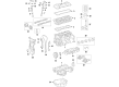
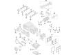
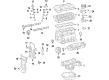
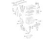
Scion Cylinder Head Gasket
OEM parts deliver unmatched quality you can rely on. They pass extensive quality control inspections. Scion produces them to the official factory specifications. This process helps prevent defects and imperfections. So you can get exceptional lifespan and a flawless fit. Need new OEM Scion Cylinder Head Gasket? You'll love our wide selection of genuine options. Shop in minutes and skip the hunt. Our prices are unbeatable, you'll save time and money. It's easy to shop and find the right piece. Our committed customer service team gives professional help from start to finish. Every part includes a manufacturer's warranty. We ship quickly, your parts will arrive fast at your door.
Scion Cylinder Head Gasket is the lock that keeps the combustion tight, keeps engines cool, strong and leak free in every mile. In 2003, Scion came out all guns blazing in the streets in bold color, with fixed price, underground music association, and a mischievous advertising campaign aimed at first-time drivers. The brand has put car shopping online through the creation of a digital cityscape, as well as through pop-up tours during concerts, which created a more game-like experience than waiting in showroom lighting. Scion demand buzzers were ensured with a limited Release Series drop which made every new color or trim a collectible without premium car prices. The new line remained small and highly personalizable and thus a Scion customer could imprint a ride with enthusiasm rather than take a ride with a bland ride. The experiments it pioneered are still reverberated in parent company showrooms and online configurators even after the badge retired in 2016. The Cylinder Head Gasket is made of multi-layer steel, which helps to keep the block and the head apart to allow combustion pressure, flow of coolant and oil circuits to remain apart to maintain power loss and overheating, but to enable the engine to reach its desired efficiency curve mile after mile. When the Cylinder Head Gasket is warped or cracked, drivers experience unusual temperature surges or white exhaust smoke at first. Early identification of the problem prevents a Scion engine from ingesting coolant and burning off pistons. Replacing it with a new Cylinder Head Gasket will regain tight compression, stable idle and confident throttle response. Since extreme pressure is put on the Cylinder Head Gasket at every second, good metallurgy is the direct measure of longer road life.
Scion Cylinder Head Gasket Parts and Q&A
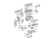
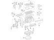
- Q: How to remove the cylinder head gasket on Scion xB?A:The removal process of the 2AZ-FE engine cylinder head gasket starts with fuel system pressure discharge first. Disconnect the cable from the negative battery terminal before waiting for 90 seconds and after ensuring prevention of Air Bag activation. Start by removing the hood through wash hose disconnect and bolt (4) deinstallation. The removal procedure starts with taking away the front right wheel in addition to both the No. 1 engine under cover and the rear engine under cover on the right side of the vehicle. Start by taking off the No. 1 engine cover sub-assembly and then draining engine coolant followed by engine oil before disconnecting the center exhaust pipe assembly. Proceed with removal of the front exhaust pipe assembly followed by the windshield wiper arm cover and the front wiper arm assemblies together with their blades. The technician should remove the hood to cowl top seal together with cowl top ventilator louvers found on both sides and also the front wiper motor and link. You should proceed to remove the outer cowl top panel and fan and generator V belt followed by the generator assembly. The radiator reserve tank assembly requires its two bolts to be removed before separation. Rephrase the following sentence, normalize verbalization when possible: Take off the air cleaner cap sub-assembly with hose together with throttle body assembly, ignition coil assembly, and spark plug. Separate the combination of cylinder head cover, oil dipstick, oil dipstick guide, bolt, and O-ring from the system. Disembark the fuel main tube before taking out the fuel delivery pipe sub-assembly. You should unfasten the camshaft timing oil control valve assembly, intake manifold and intake manifold insulator while you extract the manifold stays and the No. 1 exhaust manifold heat insulator. The exhaust manifold converter sub-assembly demands removal with both air-fuel ratio sensor connector disconnection and the elimination of 5 nuts, manifold converter, and gasket. A transmission jack enables supporting the engine to safely separate the right-hand engine mounting insulator sub-assembly using appropriate bolts and brackets. The manufacturer should execute the front engine mounting insulator sub-assembly process again. First remove the idler pulley subsystem while next operating to eliminate the oil pan subsystem through installation of new bolts for the No. 1 and No. 2 engine hangers and sling device attachment and subsequent bolt and nut removal. Localize the sealer with a cutting wheel for extracting the oil pan without affecting the contact areas. Set the No. 1 cylinder at TDC compression by aligning its crankshaft pulley with the timing mark "0" and verifying that the camshaft timing gear and sprocket alignment. The crankshaft pulley and the No. 1 chain tensioner assembly need removal but avoid rotating the crankshaft except with the chain tensioner in place. The procedure requires uninstalling the transverse engine mounting bracket as well as the V-ribbed belt tensioner assembly and crankshaft position sensor. Detaching the timing chain or belt cover sub-assembly should happen while avoiding any damage to its contacting surfaces. You must take off the No. 1 crankshaft position sensor plate and timing chain guide in addition to the chain tensioner slipper and No. 1 chain vibration damper. The technician should detach the crankshaft timing gear or sprocket with the chain sub-assembly. Lock the oil pump drive shaft sprocket by turning the crankshaft 90 degrees counterclockwise before removing the required parts of the No. 2 chain sub-assembly. The maintenance procedure includes hose disconnection of the inlet radiator as well as outlet heater water and inlet heater water and engine wire connectors removal. After removing the No. 2 camshaft and camshaft and both camshaft bearings it is essential to loosen evenly all 10 cylinder head bolts together with 10 plate washers according to a specific sequence before carefully prying off the cylinder head to remove the cylinder head gasket.
- Q: What is the importance of the cylinder head gasket during service and repair on Scion xD?A:Proper attention should be given to the 2ZR-FE cylinder head gasket since it remains a fundamental part supporting engine performance in service. Optimal engine performance with leak prevention requires both correct handling steps during service and proper installation techniques. Knowledge about individual cylinder head gasket assembly components prevents difficulties during both servicing and diagnostic processes.