×
ToyotaParts- Hello
- Login or Register
- Quick Links
- Live Chat
- Track Order
- Parts Availability
- RMA
- Help Center
- Contact Us
- Shop for
- Toyota Parts
- Scion Parts
My Garage
My Account
Cart
OEM Toyota Sienna Oxygen Sensor
Oxygen O2 Sensor- Select Vehicle by Model
- Select Vehicle by VIN
Select Vehicle by Model
orMake
Model
Year
Select Vehicle by VIN
For the most accurate results, select vehicle by your VIN (Vehicle Identification Number).
37 Oxygen Sensors found


Toyota Sienna Oxygen Sensor, Driver Side Part Number: 89467-48050
$227.75 MSRP: $325.17You Save: $97.42 (30%)Ships in 1-2 Business Days


Toyota Sienna Oxygen Sensor, Driver Side Part Number: 89465-48170
$151.92 MSRP: $215.06You Save: $63.14 (30%)Ships in 1 Business Day


Toyota Sienna Oxygen Sensor, Front Driver Side Part Number: 89467-0E240
$207.59 MSRP: $296.39You Save: $88.80 (30%)Ships in 1-2 Business Days

Toyota Sienna Oxygen Sensor, Rear Driver Side Part Number: 89465-0E210
$161.43 MSRP: $228.53You Save: $67.10 (30%)Ships in 1-3 Business Days


Toyota Sienna Oxygen Sensor, Rear Part Number: 89465-08010
$121.37 MSRP: $171.81You Save: $50.44 (30%)Ships in 1-3 Business Days
Toyota Sienna Oxygen Sensor, Front Part Number: 89465-06100
$126.65 MSRP: $179.29You Save: $52.64 (30%)Ships in 1-3 Business Days
Toyota Sienna Oxygen Sensor, Passenger Side Part Number: 89465-08030
$125.60 MSRP: $177.80You Save: $52.20 (30%)Ships in 1-2 Business Days

Toyota Sienna Oxygen Sensor, Rear Driver Side Part Number: 89465-0E040
$165.08 MSRP: $233.68You Save: $68.60 (30%)Ships in 1-3 Business Days

Toyota Sienna Oxygen Sensor, Driver Side Part Number: 89467-07030
$180.45 MSRP: $257.64You Save: $77.19 (30%)Ships in 1-3 Business Days
Toyota Sienna Oxygen Sensor, Passenger Side Part Number: 89467-08040
$199.90 MSRP: $285.41You Save: $85.51 (30%)Ships in 1-2 Business Days
Toyota Sienna Oxygen Sensor, Driver Side Part Number: 89467-06130
$216.10 MSRP: $308.54You Save: $92.44 (30%)Ships in 1-3 Business Days


Toyota Sienna Sensor, Wide Range Air Fuel Ratio, Driver Side Part Number: 89467-41040
$218.54 MSRP: $312.03You Save: $93.49 (30%)Ships in 1-2 Business Days
Toyota Sienna Sensor, Wide Range Air Fuel Ratio, Passenger Side Part Number: 89467-41021
$218.54 MSRP: $312.03You Save: $93.49 (30%)Ships in 1-2 Business Days


Toyota Sienna Sensor, Wide Range Air Fuel Ratio, Passenger Side Part Number: 89467-41030
$220.52 MSRP: $314.86You Save: $94.34 (30%)Ships in 1-3 Business Days

Toyota Sienna Oxygen Sensor, Front Passenger Side Part Number: 89467-0E140
$241.84 MSRP: $345.30You Save: $103.46 (30%)Ships in 1-3 Business Days
Toyota Sienna Sensor, Air Fuel Ratio, Driver Side Part Number: 89467-0E040
$240.09 MSRP: $342.80You Save: $102.71 (30%)Ships in 1-3 Business Days

Toyota Sienna Oxygen Sensor, Driver Side Part Number: 89465-08090
$112.33 MSRP: $157.67You Save: $45.34 (29%)Ships in 1-3 Business Days

Toyota Sienna Oxygen Sensor, Passenger Side Part Number: 89465-08070
$112.33 MSRP: $157.67You Save: $45.34 (29%)Ships in 1-3 Business Days
Toyota Sienna Oxygen Sensor, Rear Part Number: 89465-09290
$116.71 MSRP: $163.82You Save: $47.11 (29%)Ships in 1-2 Business Days

Toyota Sienna Oxygen Sensor Part Number: 89467-41011
$218.54 MSRP: $312.03You Save: $93.49 (30%)Ships in 1 Business Day
| Page 1 of 2 |Next >
1-20 of 37 Results
Toyota Sienna Oxygen Sensor
Choose genuine Oxygen Sensor that pass strict quality control tests. You can trust the top quality and lasting durability. Shopping for OEM Oxygen Sensor for your Toyota Sienna? Our website is your one-stop destination. We stock an extensive selection of genuine Toyota Sienna parts. The price is affordable so you can save more. It only takes minutes to browse and find the exact fit. Easily add to cart and check out fast. Our hassle-free return policy will keep you stress-free. We process orders quickly for swift delivery. Your parts will arrive faster, so you can get back on the road sooner.
Toyota Sienna Oxygen Sensor Parts and Q&A
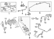
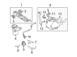
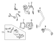
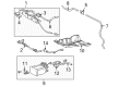
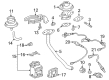
- Q: How to install the Oxygen Sensor for Bank 2 Sensor 1 on Toyota Sienna?A:Special Service Tool 09224-00010 helps in mounting the sensor onto the exhaust manifold LH using a torque of 40 Nm (408 kgf-cm, 30 ft-lbf) with the tool or 44 Nm (449 kgf-cm, 32 ft-lbf) without it under the condition that the torque wrench possesses a 30 cm (11.81 in.) fulcrum length and maintains a straight alignment with the tool. Connect the sensor connector. The Sensor 1 Bank 1 requires another installation phase with the same tool to attach it to exhaust manifold RH while applying torque specifications before connector connection. After setting down the exhaust manifold RH using new gasket and 6 nuts to 21 Nm (214 kgf-cm, 15 ft-lbf) torque you must apply a nut and bolt connection on the exhaust manifold stay to 35 Nm (357 kgf-cm, 26 ft-lbf) torque before finishing with the air fuel ratio sensor for Bank 1 Sensor 2 installation. Measurement of compression springs using vernier calipers should be 38.86 mm (1.5299 in.) and triggering a replacement if the reading is off. Use hand placement to mount a fresh gasket on the front Exhaust Pipe before hitting it smooth with a plastic mallet through a wooden block while avoiding damage by keeping proper installation orientation and preserving the gasket from reuse. At 43 Nm (440 kgf-cm, 32 ft-lbf) torques apply 2 new gaskets to the front exhaust pipe assembly through the installation of 2 nuts and 2 bolts. Mount the center exhaust pipe assembly by inserting 2 compression springs along with 2 bolts that need to be torqued to 43 Nm (438 kgf-cm, 32 ft-lbf). This process should be followed by inserting the clip before connecting the heated oxygen sensor for Bank 1 Sensor 2. An inspection for exhaust gas leaks should be conducted after connecting the cable to the negative battery terminal.
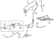
- Q: How to service and repair the heated oxygen sensor on Toyota Sienna?A:The process of servicing the heated oxygen sensor includes disconnecting the negative battery terminal cable as the first step for 2GR-FE emission control system in 4WD vehicles. The heated oxygen sensor for Bank 1 Sensor 2 requires disconnecting the sensor connector which is beneath the center console and subsequent removal with tool 09224-00010. The removal process starts by disconnecting the heated oxygen sensor connector for Bank 2 Sensor 2 after which the technician should continue by uninstalling the 2 bolts and 4 nuts holding the assembly together. Proceed by removing Bank 2 Sensor 2 from the front Exhaust Pipe assembly while using Special Service Tool.


Related Toyota Sienna Parts
 Toyota Sienna Ignition Coil
 Toyota Sienna Knock Sensor
 Toyota Sienna Radiator Fan Relay
 Toyota Sienna Throttle Position Sensor
 Toyota Sienna Cooling Fan Relay
 Toyota Sienna Crankcase Breather Hose
 Toyota Sienna Crankshaft Position Sensor
 Toyota Sienna Daytime Running Light Relay
 Toyota Sienna Headlight Relay
 Toyota Sienna Ignition Control Module
 Toyota Sienna PCV Hose
 Toyota Sienna Relay