×
ToyotaParts- Hello
- Login or Register
- Quick Links
- Live Chat
- Track Order
- Parts Availability
- RMA
- Help Center
- Contact Us
- Shop for
- Toyota Parts
- Scion Parts
My Garage
My Account
Cart
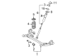
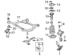
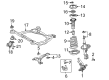
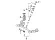
OEM Toyota Sienna Coil Springs
Strut Spring- Select Vehicle by Model
- Select Vehicle by VIN
Select Vehicle by Model
orMake
Model
Year
Select Vehicle by VIN
For the most accurate results, select vehicle by your VIN (Vehicle Identification Number).
36 Coil Springs found


Toyota Sienna Coil Spring, Rear Part Number: 48231-08051
$132.06 MSRP: $186.94You Save: $54.88 (30%)Ships in 1-3 Business Days

Toyota Sienna Coil Spring, Front Part Number: 48131-AE040
$137.70 MSRP: $194.92You Save: $57.22 (30%)Ships in 1-3 Business Days
Toyota Sienna Coil Spring, Rear Part Number: 48231-08011
$144.16 MSRP: $204.08You Save: $59.92 (30%)Ships in 1 Business Day


Toyota Sienna Coil Spring, Rear Part Number: 48231-AE031
$142.28 MSRP: $201.42You Save: $59.14 (30%)Ships in 1-3 Business Days

Toyota Sienna Coil Spring, Front Part Number: 48131-AE033
$153.91 MSRP: $217.88You Save: $63.97 (30%)Ships in 1-3 Business Days
Toyota Sienna Coil Spring, Front Part Number: 48131-AE043
$162.02 MSRP: $229.36You Save: $67.34 (30%)Ships in 1-3 Business DaysToyota Sienna Coil Spring, Rear Part Number: 48231-08041
$125.48 MSRP: $177.63You Save: $52.15 (30%)Ships in 1-3 Business DaysToyota Sienna Coil Spring, Rear Part Number: 48231-08071
$134.88 MSRP: $190.94You Save: $56.06 (30%)Ships in 1-3 Business Days

Toyota Sienna Coil Spring, Rear Part Number: 48231-08061
$134.88 MSRP: $190.94You Save: $56.06 (30%)Ships in 1-3 Business DaysToyota Sienna Coil Spring, Front Part Number: 48131-AE030
$153.91 MSRP: $217.88You Save: $63.97 (30%)Ships in 1-3 Business Days
Toyota Sienna Coil Spring, Rear Part Number: 48231-AE041
$160.96 MSRP: $227.86You Save: $66.90 (30%)Ships in 1-3 Business Days
Toyota Sienna Coil Spring, Rear Part Number: 48231-08080
$84.12 MSRP: $118.08You Save: $33.96 (29%)Ships in 1-3 Business DaysToyota Sienna Coil Spring, Rear Part Number: 48231-08090
$85.78 MSRP: $120.41You Save: $34.63 (29%)Ships in 1-3 Business Days
Toyota Sienna Coil Spring, Rear Part Number: 48231-08110
$87.20 MSRP: $122.41You Save: $35.21 (29%)Ships in 1-3 Business DaysToyota Sienna Coil Spring, Rear Part Number: 48231-08120
$90.05 MSRP: $126.40You Save: $36.35 (29%)Ships in 1-3 Business Days
Toyota Sienna Coil Spring, Front Part Number: 48131-08060
$102.49 MSRP: $143.86You Save: $41.37 (29%)Ships in 1-3 Business Days
Toyota Sienna Coil Spring, Front Part Number: 48131-08050
$102.49 MSRP: $143.86You Save: $41.37 (29%)Ships in 1-2 Business DaysToyota Sienna Coil Spring, Front Part Number: 48131-08090
$102.61 MSRP: $144.03You Save: $41.42 (29%)Ships in 1-3 Business DaysToyota Sienna Coil Spring, Front Part Number: 48131-08080
$102.61 MSRP: $144.03You Save: $41.42 (29%)Ships in 1-3 Business DaysToyota Sienna Coil Spring, Front Part Number: 48131-08100
$108.89 MSRP: $152.85You Save: $43.96 (29%)Ships in 1-3 Business Days
| Page 1 of 2 |Next >
1-20 of 36 Results
Toyota Sienna Coil Springs
Choose genuine Coil Springs that pass strict quality control tests. You can trust the top quality and lasting durability. Shopping for OEM Coil Springs for your Toyota Sienna? Our website is your one-stop destination. We stock an extensive selection of genuine Toyota Sienna parts. The price is affordable so you can save more. It only takes minutes to browse and find the exact fit. Easily add to cart and check out fast. Our hassle-free return policy will keep you stress-free. We process orders quickly for swift delivery. Your parts will arrive faster, so you can get back on the road sooner.
Coil Springs; found in Toyota Sienna motors mostly provide support to the weight of the vehicle and assist in handling shocks which may be caused by, for example, bumps. Some of the signs that your car has worn or broken coil springs are saggings, bottoming out and unusual wearing off of the tires. Horsepower increasing kits and replacement springs include new ride height and quality; the options incorporate OEM, variable, and cargo coils for the loads. Coil springs vary in height and rates and therefore influences the car handling and tractions. They come in linear rate, progressive, and dual rate, thus providing different stiffness to suit a vehicle's requirements. When it comes to further adjustment of the lowering kit, there is the option of using adjustable coilovers or height adjustable springs.
Toyota Sienna Coil Springs Parts and Q&A
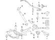
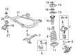
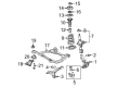
- Q: How to remove and replace the rear coil springs on Toyota Sienna?A:The first step in spring replacement is to take off the wheel positioned at the back of the vehicle. The process to remove the rear axle beam assembly bracket begins with unconnecting the skid control sensor connector and removing the bolt attaching the bracket to the assembly for vehicles equipped with 2WD. The speed sensor rear LH will need its bolt removed during 4WD separation while a similar process should follow for the speed sensor rear RH. The Exhaust Pipe assembly tail needs to be taken off followed by removing the propeller W/center bearing shaft assembly for 4WD vehicles. A matchmarking process on the assembly with the Differential flange reveals the necessary procedure for removing 4 nuts and 4 washers. The second part of this procedure entails performing the same operations on the rear Drive Shaft assembly RH. The 4WD differential carrier assembly rear requires removal before separating Parking Brake Cable assembly No.3 through its two bolts. The procedure should be repeated to separate parking brake cable assembly Number 2. Using tool 09023-00101 separate brake tube No.2 from the flexible hose by catching brake fluid into a container then unfasten the clip and bolt to fully detach the brake tube from the rear axle beam assembly. The same tool applies to separate rear brake tube No.1. The fuel tank filler hose cover requires removal of 2 bolts together with 3 screws and 3 nuts then 3 additional bolts. Detach thetwo bolts on the rear floor No.2 crossmember brace LH and then do the same on the right-hand side. You must hold the nut stationary to avoid axle beam rotation during loosening but will not remove either the bolt or the nut. A jack should support the rear axle beam assembly before removing the bolt which will separate the Shock Absorber assembly rear LH followed by the RH side. The process of removing the coil spring rear LH demands the placement of a shop rug between spring and assembly followed by gradual jack lowering for coil spring removal. The final step requires removal of the rear coil spring insulator upper LH from the coil spring rear LH.
- Q: How to install the rear coil springs and associated components on Toyota Sienna?A:When installing the rear coil spring start by connecting the rear coil spring insulator upper LH to the coil spring rear LH. Place a shop rug on the rear axle beam assembly and position the coil spring rear LH while making sure its lower end rests inside the spring lower seat gap. Raise the jack while connecting the Shock Absorber assembly rear LH to the rear axle beam assembly and secure its nut with a temporary torque. You should repeat the same shock absorber assembly rear RH installation process. The installation of rear brake tube No.2 requires attaching the flexible hose and clip followed by using Special Service Tool: 09023-00101 to fasten the brake tube to the flexible hose until it reaches 15 Nm (153 kgf-cm, 11 ft-lbf) torque. Finish by installing the bolt to 8.0 Nm (82 kgf-cm, 71 in-lbf) torque. Rephrase this step through the use of Service Tool 09023-00101 during rear brake tube No.1 installation on the RH side following the LH-side installation sequence. Thirdly secure Parking Brake Cable assembly No.3 to the rear axle beam assembly with 2 bolts then finalize connection by tightening them to 8.0 Nm (82 kgf-cm, 71 in-lbf). Repeat the same process for parking brake cable assembly No.2 installation on the right-hand side. Install the Differential carrier assembly rear (for 4WD) and follow it with the rear Drive Shaft assembly LH using 4 washers and 4 nuts which need to be tightened to 56 Nm (571 kgf-cm, 41 ft-lbf) and complete the installation by adding the rear drive shaft assembly RH. Old the propeller unit alongside center bearing shaft assembly (for 4WD) then attach the speed sensor rear LH by bolting it to a torque of 8.0 Nm (82 kgf-cm, 71 in-lbf) while conducting the same procedure for the speed sensor rear RH. Follow the same procedure used on the left side to connect the skid control sensor wire through its connector then bolt and bracket attachment to the rear axle beam assembly using an 8.0 Nm (82 kgf-cm, 71 in-lbf) torque value. Place the Exhaust Pipe assembly tail into position then bleed the brake tubing while checking the brake fluid quantity in the reservoir. Install the rear wheel along with lowering the vehicle until the shock absorbers reach their tightness limit of 103 Nm (1,050 kgf-cm, 76 ft-lbf). After stabilization, bounce the vehicle for suspension stabilization. After positioning the shock absorber nut at the correct spot complete the full tightening process while supporting the rear axle beam assembly with an appropriate jack and applying 90 kg (198 lb) of weight distribution between the shocks using 234 mm (9.2 in.) for 2WD and 258 mm (10.2 in.) for 4WD models before torquing the nut to 115 Nm (1,173 kgf-cm, 85 ft-lbf). Perform a full procedure for tightening the shock absorber assembly rear RH. The rear axle beam assembly requires total tightening while supporting the frame with stable procedures and applying 135 Nm force (1,377 kgf-cm, 100 ft-lbf) torque to the bolt instead of the nut. Make sure the vehicle height remains at the shock absorber's full tightening position. Secure the rear floor No.2 crossmember brace LH using two bolts that reach 28 Nm (286 kgf-cm, 21 ft-lbf) then do the same for the RH side. The last step involves setting up the fuel tank filler hose cover through the fuel tank filler pipe protector along with 2 bolts, 3 screws and 3 nuts, and finally fastening the hose cover with 3 bolts torqued to 5.0 Nm (51 kgf-cm, 44 in-lbf). Examine the wheel alignment of the rear wheels and carry out examinations on the ABS speed sensor signal according to proper procedures for ABS with EBD system and ABS with EBD & BA & TRAC & VSC system.


Related Toyota Sienna Parts
 Toyota Sienna Sway Bar Bushing
 Toyota Sienna Axle Beam Mount
 Toyota Sienna Control Arm Bushing
 Toyota Sienna Crossmember Bushing
 Toyota Sienna CV Boot
 Toyota Sienna Lateral Link
 Toyota Sienna Steering Knuckle
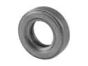 Toyota Sienna Strut Bearing
 Toyota Sienna Strut Mounts
 Toyota Sienna Sway Bars
 Toyota Sienna Trailing Arm
 Toyota Sienna Trailing Arm Bushing