×
ToyotaParts- Hello
- Login or Register
- Quick Links
- Live Chat
- Track Order
- Parts Availability
- RMA
- Help Center
- Contact Us
- Shop for
- Toyota Parts
- Scion Parts
My Garage
My Account
Cart
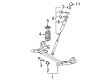
OEM 2004 Toyota Sienna Coil Springs
Strut Spring- Select Vehicle by Model
- Select Vehicle by VIN
Select Vehicle by Model
orMake
Model
Year
Select Vehicle by VIN
For the most accurate results, select vehicle by your VIN (Vehicle Identification Number).
4 Coil Springs found


2004 Toyota Sienna Coil Spring, Rear
Part Number: 48231-AE031$142.28 MSRP: $201.42You Save: $59.14 (30%)Ships in 1-3 Business DaysProduct Specifications- Other Name: Spring, Coil, Rear; Coil Spring, Rear; Coil Spring Kit Rear; Coil Spring Set; Coil Springs; Spring; Spring, Coil, Rear Passenger Side; Spring, Coil, Rear Driver Side
- Position: Rear
- Replaces: 48231-AE030
- Item Weight: 4.20 Pounds
- Item Dimensions: 17.0 x 10.8 x 5.7 inches
- Condition: New
- Fitment Type: Direct Replacement
- SKU: 48231-AE031
- Warranty: This genuine part is guaranteed by Toyota's factory warranty.


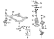
2004 Toyota Sienna Coil Spring, Front
Part Number: 48131-AE040$137.70 MSRP: $194.92You Save: $57.22 (30%)Ships in 1-3 Business DaysProduct Specifications- Other Name: Spring, Coil, Front; Coil Spring, Front; Coil Spring Set; Coil Springs; Spring; Spring, Front Coil, Passenger Side; Spring, Front Coil, Driver Side
- Position: Front
- Item Weight: 6.70 Pounds
- Item Dimensions: 16.1 x 7.0 x 5.9 inches
- Condition: New
- Fitment Type: Direct Replacement
- SKU: 48131-AE040
- Warranty: This genuine part is guaranteed by Toyota's factory warranty.

2004 Toyota Sienna Coil Spring, Rear
Part Number: 48231-AE041$156.26 MSRP: $221.21You Save: $64.95 (30%)Ships in 1-3 Business DaysProduct Specifications- Other Name: Spring, Coil, Rear; Coil Spring, Rear; Coil Spring Kit Rear; Coil Spring Set; Coil Springs; Spring; Spring, Coil, Rear Passenger Side; Spring, Coil, Rear Driver Side
- Manufacturer Note: PASSENGERS CAR & R.V.-MOBILITY BASE VEICLE
- Position: Rear
- Replaces: 48231-AE040
- Item Weight: 11.60 Pounds
- Item Dimensions: 16.7 x 10.8 x 5.7 inches
- Condition: New
- Fitment Type: Direct Replacement
- SKU: 48231-AE041
- Warranty: This genuine part is guaranteed by Toyota's factory warranty.

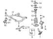
2004 Toyota Sienna Coil Spring, Front
Part Number: 48131-AE030$149.33 MSRP: $211.39You Save: $62.06 (30%)Ships in 1-3 Business DaysProduct Specifications- Other Name: Spring, Coil, Front; Coil Spring, Front; Coil Spring Kit Front; Coil Spring Set; Coil Springs; Spring; Spring, Front Coil, Passenger Side; Spring, Front Coil, Driver Side
- Position: Front
- Item Weight: 6.70 Pounds
- Item Dimensions: 15.5 x 7.1 x 5.9 inches
- Condition: New
- Fitment Type: Direct Replacement
- SKU: 48131-AE030
- Warranty: This genuine part is guaranteed by Toyota's factory warranty.
2004 Toyota Sienna Coil Springs
Looking for affordable OEM 2004 Toyota Sienna Coil Springs? Explore our comprehensive catalogue of genuine 2004 Toyota Sienna Coil Springs. All our parts are covered by the manufacturer's warranty. Plus, our straightforward return policy and speedy delivery service ensure an unparalleled shopping experience. We look forward to your visit!
2004 Toyota Sienna Coil Springs Parts Q&A
- Q: How to replace the rear left coil springs on 2004 Toyota Sienna?A: First detach the wheel from the rear position and then pull out the connector securing the skid control sensor wire for 2WD drive types followed by removing the bolt attached to the bracket from the rear axle beam assembly. Separate the rear left speed sensor for 4WD drive systems by losing its connecting bolt followed by removing the sensor at the rear right. For the replacement of the rear drive shaft assemblies start by first removing the exhaust pipe from both drive types and then moving to eliminate the propeller assembly including center bearing shaft before separating the left rear drive shaft assembly by recording its initial position and removing its attached nuts and washers. Repeat this process for the right side of the drive shaft assembly. Execute the procedure again for the rear drive shaft assembly on the right side. The procedure continues by removing the rear differential carrier assembly followed by disassembly of parking brake cable assembly No.3 with two bolts and parking brake cable assembly No.2. The process to break off rear brake tube No.2 requires Special Service Tool: 09023-00100 to unlink the tube from its flexible hose while capturing draining brake fluid before removing the clip and bolt for full separation. The same procedure should be performed on rear brake tube No.1. The fuel tank filler hose cover requires three screws three nuts along with two bolts before the final step of removing three bolts. The rear floor No.2 crossmember brace left and right needs two bolts removed at each end. Smoothing the bolts on the rear axle beam assembly while still keeping them in place would then require support from the nut through firm handling. First use a jack to support the rear axle beam assembly. After that separate the rear left shock absorber assembly by removing its bolt. Perform the same process on the rear right shock absorber assembly. The process to remove the rear left coil spring requires placing shop rags between the assembly components and carefully lowering the jack vehicle slowly. Install the rear coil spring insulator upper left segment onto its original position on the coil spring. The installation of the rear left coil spring requires a shop rag placed next to the rear axle beam assembly for proper fitting of its lower end into the spring lower seat. Raising the jack while connecting the rear left shock absorber assembly then temporarily tighten the nut before moving to the rear right side. Engineers must use Special Service Tool: 09023-00100 to join the flexible hose to brake tube No.2. They should torque the connection to 15 Nm (153 kgf-cm, 11 ft. lbs.) before inserting the bolt with 8.0 Nm (82 kgf-cm, 71 inch lbs. torque). Seal the same procedure to rear brake tube No.1. Fasten both bolts that secure parking brake cable assembly No.3 with 8.0 Nm of torque (82 kgf-cm) then secure No.2 with matching bolts and torque value. Proceed with installing the rear differential carrier assembly followed by installing the rear drive shaft assembly left with four washers and nuts and torquing them to 56 Nm (571 kgf-cm, 41 ft. lbs.). Then repeat this operation for the rear drive shaft assembly right. The installation order includes putting in the propeller assembly followed by center bearing shaft then installing and torquing rear left speed sensor bolts to 8.0 Nm (82 kgf-cm, 71 inch lbs.) before moving on to the rear right speed sensor. To connect the skid control sensor wire properly you must install its bolt together with its bracket onto the rear axle beam assembly while tightening it to a torque of 8.0 Nm (82 kgf-cm, 71 inch lbs.). Install the exhaust pipe assembly while completing brake pipe bleeding before checking the fluid level of the brake reservoir. To stabilize the suspension position the rear wheel before lowering the vehicle while bouncing it several times up and down. Install a torque wrench on the rear left shock absorber assembly nut until it reaches 115 Nm (1,173 kgf-cm, 85 ft. lbs.). Then repeat the installation process on the rear right side. The rear axle beam assembly bolt should be tightened fully to 135 Nm (1,377 kgf-cm, 100 ft. lbs.) but always focus on the bolt itself while avoiding the nut to prevent any vehicle height changes. The installer should mount the left rear floor No.2 crossmember brace with two bolts torqued to 28 Nm (286 kgf-cm, 21 ft. lbs.) then verify the right side with the same procedure. Install the fuel tank filler hose cover with its protector and all necessary hardware while torqueing the cover to 5.0 Nm (51 kgf-cm, 44 inch lbs.). Both ABS with EBD and ABS with EBD & BA & TRAC & VSC system signals must be checked before inspecting the rear wheel alignment.
Related 2004 Toyota Sienna Parts
 2004 Toyota Sienna Sway Bar Bushing
 2004 Toyota Sienna Axle Beam Mount
 2004 Toyota Sienna Bump Stop
 2004 Toyota Sienna Coil Spring Insulator
 2004 Toyota Sienna Control Arm Bushing
 2004 Toyota Sienna Crossmember Bushing
 2004 Toyota Sienna Front Cross-Member
 2004 Toyota Sienna Shock Absorber
 2004 Toyota Sienna Shock And Strut Mount
 2004 Toyota Sienna Shock and Strut Boot
 2004 Toyota Sienna Steering Knuckle
 2004 Toyota Sienna Sway Bar Bracket