×
ToyotaParts- Hello
- Login or Register
- Quick Links
- Live Chat
- Track Order
- Parts Availability
- RMA
- Help Center
- Contact Us
- Shop for
- Toyota Parts
- Scion Parts
My Garage
My Account
Cart
OEM Toyota RAV4 Brake Caliper
Caliper- Select Vehicle by Model
- Select Vehicle by VIN
Select Vehicle by Model
orMake
Model
Year
Select Vehicle by VIN
For the most accurate results, select vehicle by your VIN (Vehicle Identification Number).
24 Brake Calipers found


Toyota RAV4 Caliper Assembly, Driver Side Part Number: 47750-06321
$132.06 MSRP: $186.94You Save: $54.88 (30%)Ships in 1-2 Business Days

Toyota RAV4 Caliper Assembly, Rear Driver Side Part Number: 47850-42061
$140.87 MSRP: $199.42You Save: $58.55 (30%)Ships in 1-3 Business Days
Toyota RAV4 Caliper Assembly, Passenger Side Part Number: 47830-42061
$140.87 MSRP: $199.42You Save: $58.55 (30%)Ships in 1-3 Business Days


Toyota RAV4 Caliper, Driver Side Part Number: 47750-02410
$196.76 MSRP: $280.92You Save: $84.16 (30%)Ships in 1-3 Business Days

Toyota RAV4 Caliper, Passenger Side Part Number: 47730-02410
$196.76 MSRP: $280.92You Save: $84.16 (30%)Ships in 1-3 Business Days


Toyota RAV4 Caliper, Driver Side Part Number: 47750-0R010
$111.50 MSRP: $156.51You Save: $45.01 (29%)Ships in 1-3 Business Days

Toyota RAV4 Caliper, Passenger Side Part Number: 47730-0R010
$111.50 MSRP: $156.51You Save: $45.01 (29%)Ships in 1-3 Business Days
Toyota RAV4 Cylinder Assembly, Front Disc Brake, Passenger Side Part Number: 47730-33381
$132.06 MSRP: $186.94You Save: $54.88 (30%)Ships in 1-3 Business Days
Toyota RAV4 Caliper Assembly, Driver Side Part Number: 47750-42091
$132.06 MSRP: $186.94You Save: $54.88 (30%)Ships in 1-3 Business Days
Toyota RAV4 Cylinder Assembly, Disc Brake, Driver Side Part Number: 47750-33311
$132.06 MSRP: $186.94You Save: $54.88 (30%)Ships in 1-3 Business DaysToyota RAV4 Caliper Assembly, Passenger Side Part Number: 47730-42091
$132.06 MSRP: $186.94You Save: $54.88 (30%)Ships in 1-3 Business DaysToyota RAV4 Caliper Assembly, Passenger Side Part Number: 47730-06321
$132.06 MSRP: $186.94You Save: $54.88 (30%)Ships in 1-3 Business Days
Toyota RAV4 Cylinder Assembly, Disc Brake, Driver Side Part Number: 47750-12A70
$157.79 MSRP: $223.37You Save: $65.58 (30%)Ships in 1-3 Business DaysToyota RAV4 Cylinder Assembly, Front Disc Brake, Passenger Side Part Number: 47730-12A70
$157.79 MSRP: $223.37You Save: $65.58 (30%)Ships in 1-2 Business Days
Toyota RAV4 Caliper Assembly, Passenger Side Part Number: 47730-42130
$194.89 MSRP: $278.26You Save: $83.37 (30%)Ships in 1-3 Business DaysToyota RAV4 Cylinder Assembly, Disc Brake, Driver Side Part Number: 47750-42130
$199.90 MSRP: $285.42You Save: $85.52 (30%)Ships in 1-3 Business Days
Toyota RAV4 Caliper Assembly, Driver Side Part Number: 47750-42010
$263.39 MSRP: $376.07You Save: $112.68 (30%)Ships in 1-3 Business DaysToyota RAV4 Caliper Assembly, Passenger Side Part Number: 47730-42010
$263.39 MSRP: $376.07You Save: $112.68 (30%)Ships in 1-3 Business Days
Toyota RAV4 Caliper Assembly, Driver Side Part Number: 47750-42040
$283.55 MSRP: $404.84You Save: $121.29 (30%)Ships in 1-3 Business DaysToyota RAV4 Caliper Assembly, Passenger Side Part Number: 47730-42040
$283.55 MSRP: $404.84You Save: $121.29 (30%)Ships in 1-3 Business Days
| Page 1 of 2 |Next >
1-20 of 24 Results
Toyota RAV4 Brake Caliper
Choose genuine Brake Caliper that pass strict quality control tests. You can trust the top quality and lasting durability. Shopping for OEM Brake Caliper for your Toyota RAV4? Our website is your one-stop destination. We stock an extensive selection of genuine Toyota RAV4 parts. The price is affordable so you can save more. It only takes minutes to browse and find the exact fit. Easily add to cart and check out fast. Our hassle-free return policy will keep you stress-free. We process orders quickly for swift delivery. Your parts will arrive faster, so you can get back on the road sooner.
Toyota RAV4 Brake Caliper Parts and Q&A
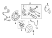
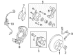
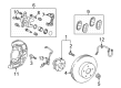
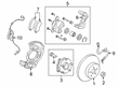
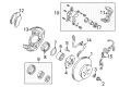
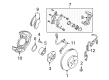
- Q: How to service the rear brake caliper on Toyota RAV4?A:Begin service of the rear brake caliper by first removing the rear wheel and applying torque to 103 Nm (1,050 kgf-cm, 76 ft.lbs). The service of the rear brake caliper requires hose disconnect by replacing its union bolt and 2 gaskets with new ones and catching drainage brake fluid in a container before securing the hose lock inside the caliper's lock hole with a final torque of 30 Nm (310 kgf-cm, 22 ft. lbs.). It is necessary to remove the caliper after uninstalling the 2 installation bolts with 44 Nm (449 kgf-cm, 33 ft. lbs.) torque strength followed by removal of the Brake Pads through pad protector and clip then the 2 pad guide pins and anti-rattle spring before extracting the 2 pads with 4 anti-squeal shims. Use a screwdriver to disassemble the set ring and cylinder boot before placing a cloth between the piston and caliper and then remove the piston with compressed air while avoiding placing fingers in front of it. A screwdriver removes the piston seal so you can extract the 2 sliding pins along with their 3 dust boots. Examine the pad lining thickness with a ruler to confirm it exceeds 1.0 mm (0.039 in.) minimum, also inspect the disc with a micrometer and replace it if its thickness falls below 8.0 mm (0.317 in.). To minimize runout the disc should be measured with a dial indicator at 10 mm (0.39 in.) from its outer edge. Any reading higher than 0.10 mm (0.0039 in.) requires readjustment through hub nut removal followed by disc turning and reinstallation at 103 Nm (1,050 kgf-cm, 76 ft. lbs.) until minimal runout reading is achieved. Replace the disc because its minimum runout measure is above 0.05 mm (0.0020 in.). The reverse disassembly process guides assembly with the application of specified parts lubricated by lithium soap base glycol grease followed by step-by-step installation in the opposite order of removal. The process ends by filling brake fluid into the reservoir followed by brake system bleeding before verifying no fluid leakage occurs.
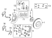
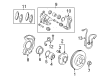
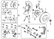
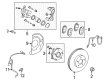
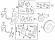
- Q: How to service and repair the front brake caliper on Toyota RAV4?A:The first step to service the front brake caliper involves disconnecting the flexible hose by removing its union bolt together with 2 gaskets. Verify that brake fluid drains into a container before torquing the union bolt to 30 Nm (310 kgf-cm, 22 ft. lbs.). During reinstallation, use 2 new gaskets and secure the flexible hose lock into the caliper lock hole. After holding the sliding pin begin unfastening the two installation bolts until the caliper is free from the torque plate. After removing the Brake Pads, their attached anti-squeal shims together with the 4 pad support plates should be discarded. To disassemble the unit begin by removing the cylinder boot set ring and cylinder boot with a screwdriver before inserting a cloth between piston and caliper for compressed air removal of the piston which requires avoiding finger placement in front of the piston. Apply a screwdriver to extract the piston seal and proceed to remove the two sliding pins along with their two dust boots. Regular inspection requires pad lining thickness measurement with a ruler at 12.0 mm (0.472 in.) standar d thickness while keeping 1.0 mm (0.039 in.) as the minimum; pad replacement is needed when meeting or falling under minimum thickness or showing severe uneven pad wear. A micrometer should measure disc thickness which must have a standard size of 25.0 mm (0.984 in.) and a minimum threshold of 23.0 mm (0.906 in.). Consequences of meeting or falling below the minimum threshold or revealing scoring or uneven wear require disc replacement or possible grinding. To measure disc runout use a dial indicator 10 mm (0.39 in.) from the edge while 0.05 mm (0.0020 in.) runout stands as the maximum tolerance; inspect bearing play and axle hub runout before performing necessary adjustment or grinding to the disc. Every adjustment requires removal of both knuckle bolts along with the torque plate followed by disc hub nuts until the disc obtains a 1/5 rotation beyond its original orientation before torquing the hub nuts to 103 Nm (1,050 kgf-cm, 76 ft. lbs.). Follow this procedure again to achieve minimum runout levels under 0.05 mm (0.0020 in.) then torque the mounting bolts to 106 Nm (1,090 kgf-cm, 78 ft. lbs.) while using the torque plate. The process of reassembly must be conducted in reverse order of disassembling steps while applying lithium soap base glycol grease to designated parts before their installation in the correct sequence of removal steps; post installation involves fluid addition into the brake reservoir followed by system bleeding then leak inspection.


Related Toyota RAV4 Parts
 Toyota RAV4 Brake Pads
 Toyota RAV4 Parking Brake Cable
 Toyota RAV4 Wheel Hub
 Toyota RAV4 Brake Drum
 Toyota RAV4 Brake Rotor
 Toyota RAV4 Backing Plate
 Toyota RAV4 Brake Caliper Bracket
 Toyota RAV4 Brake Fluid Pump
 Toyota RAV4 Brake Shoe Set
 Toyota RAV4 Parking Brake Shoes
 Toyota RAV4 Wheel Cylinder Repair Kit
 Toyota RAV4 Wheel Stud