×
ToyotaParts- Hello
- Login or Register
- Quick Links
- Live Chat
- Track Order
- Parts Availability
- RMA
- Help Center
- Contact Us
- Shop for
- Toyota Parts
- Scion Parts
My Garage
My Account
Cart
OEM Toyota Matrix Coil Springs
Strut Spring- Select Vehicle by Model
- Select Vehicle by VIN
Select Vehicle by Model
orMake
Model
Year
Select Vehicle by VIN
For the most accurate results, select vehicle by your VIN (Vehicle Identification Number).
15 Coil Springs found


Toyota Matrix Coil Spring, Front Part Number: 48131-AB060
$74.05 MSRP: $103.94You Save: $29.89 (29%)Ships in 1-3 Business Days


Toyota Matrix Coil Spring, Rear Part Number: 48231-AB010
$78.67 MSRP: $110.43You Save: $31.76 (29%)Ships in 1-3 Business Days
Toyota Matrix Coil Spring, Front Part Number: 48131-02D00
$57.61 MSRP: $80.19You Save: $22.58 (29%)Ships in 1-3 Business Days
Toyota Matrix Coil Spring, Front Part Number: 48131-02D40
$61.25 MSRP: $85.98You Save: $24.73 (29%)Ships in 1-3 Business DaysToyota Matrix Coil Spring, Front Part Number: 48131-02D20
$63.15 MSRP: $88.64You Save: $25.49 (29%)Ships in 1-3 Business DaysToyota Matrix Coil Spring, Front Part Number: 48131-02D10
$61.37 MSRP: $86.15You Save: $24.78 (29%)Ships in 1-3 Business DaysToyota Matrix Coil Spring, Front Part Number: 48131-AB090
$69.48 MSRP: $97.52You Save: $28.04 (29%)Ships in 1-3 Business DaysToyota Matrix Coil Spring, Front Part Number: 48131-AB050
$70.14 MSRP: $98.46You Save: $28.32 (29%)Ships in 1-3 Business Days
Toyota Matrix Coil Spring, Rear Part Number: 48231-02730
$70.85 MSRP: $99.45You Save: $28.60 (29%)Ships in 1-3 Business DaysToyota Matrix Coil Spring, Front Part Number: 48131-02D80
$72.63 MSRP: $101.94You Save: $29.31 (29%)Ships in 1-3 Business DaysToyota Matrix Coil Spring, Front Part Number: 48131-02D50
$75.00 MSRP: $105.28You Save: $30.28 (29%)Ships in 1-3 Business Days
Toyota Matrix Coil Spring, Rear Part Number: 48231-02740
$76.42 MSRP: $107.27You Save: $30.85 (29%)Ships in 1-3 Business Days
Toyota Matrix Coil Spring, Rear Part Number: 48231-02700
$81.16 MSRP: $113.92You Save: $32.76 (29%)Ships in 1-3 Business Days
Toyota Matrix Coil Spring, Rear Part Number: 48231-02330
$84.12 MSRP: $118.08You Save: $33.96 (29%)Ships in 1-3 Business Days
Toyota Matrix Coil Spring, Front Part Number: 48135-02060
$90.94 MSRP: $127.64You Save: $36.70 (29%)Ships in 1-3 Business Days
Toyota Matrix Coil Springs
Choose genuine Coil Springs that pass strict quality control tests. You can trust the top quality and lasting durability. Shopping for OEM Coil Springs for your Toyota Matrix? Our website is your one-stop destination. We stock an extensive selection of genuine Toyota Matrix parts. The price is affordable so you can save more. It only takes minutes to browse and find the exact fit. Easily add to cart and check out fast. Our hassle-free return policy will keep you stress-free. We process orders quickly for swift delivery. Your parts will arrive faster, so you can get back on the road sooner.
Toyota Matrix Coil Springs Parts and Q&A
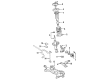
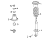
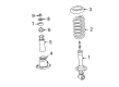
- Q: How to overhaul the front coil springs on Toyota Matrix?A:The first step to overhaul the front coil spring requires wheel removal from the front end. Disconnect the front stabilizer link assembly LH after removing its nut and releasing it from the Shock Absorber assembly front LH by utilizing a hexagon (6 mm) wrench on the stud to stop the ball joint turning if necessary. As a next step remove the front flexible hose; models equipped with ABS will require unscrewing the bolt to detach front flexible hose No. 1 and Speed Sensor front LH while models without ABS require only unscrewing the bolt to disconnect the front flexible hose. The process requires you to detach the front shock absorber with coil spring by removing the two bolts and nuts from the lower side and three nuts from the upper side of the shock absorber assembly front LH while stopping the bolt from rotating while you loosen the nut. Fasten the front shock absorber to the vise through two bolts and nuts securing the bracket at the lower side. The removal process begins by taking out the front suspension support dust cover LH and proceeding with front coil spring LH compression via Special Service Tool: 09727-30021. An impact wrench should not be used because it may damage the tool. Through the use of Special Service Tool: 09729-22031, grasp the front coil spring seat upper LH while you remove the nut leading to removal of the front suspension support sub-assembly LH, front suspension support LH dust seal, front coil spring seat upper LH, front coil spring insulator upper LH, front coil spring LH, front spring bumper LH, and front coil spring insulator lower LH. Examine the shock absorber assembly front LH by compressing and extending the shock absorber rod to check for abnormal resistance and abnormal noise which requires a new unit. For shock absorber assembly front LH installation, lower LH front coil spring insulator should be placed onto the shock absorber assembly front LH followed by the front spring bumper LH attachment to shock absorber piston rod. Use Special Service Tool to compress the front coil spring LH before installing it onto the shock absorber assembly front LH so it fits into the gap of the spring lower seat. The installation sequence is front coil spring insulator upper LH followed by front coil spring seat upper LH with its mark oriented toward the outside of the vehicle and finally front suspension support LH dust seal and front suspension support sub-assembly LH. Use Special Service Tool: 09729-22031 to tighten the new nut which secures the front coil spring seat upper LH to 47 Nm (479 kgf-cm, 35 ft. lbs.) before removing the tool. Install the front suspension support dust cover LH on the assembly while applying MP grease No.2 to the sub-assembly LH but avoid putting it on the rubber surface of the upper support. The shock absorber coil spring assembly requires installation of two bolts and three nuts on which the nut torque must be set at 39 Nm (398 kgf-cm, 29 ft. lbs.) while the bolt torque should be kept at 220 Nm (2,243 kgf-cm, 162 ft. lbs.) while preventing bolt rotation during nut torquing. The front flexible hose needs installation with 29 Nm (296 kgf-cm, 21 ft. lbs.) torque for both ABS and non-ABS models before installing the front stabilizer link assembly LH with the nut and applying 74 Nm (755 kgf-cm, 55 ft. lbs.) torque using a hexagon wrench (6 mm). The next step involves putting back the front wheel before it gets torqued to 103 Nm (1,050 kgf-cm, 76 ft. lbs.) followed by an examination and correction of the front wheel alignment. When discarding the shock absorber assembly front LH owners must fully extend the shock absorber piston rod before drilling a hole in the cylinder which discharges the gas inside while making sure to avoid flying chips and understanding that the gas exhibits none of the poisonous properties due to its colorlessness.
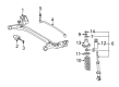
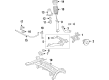
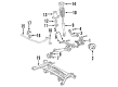
- Q: How to overhaul the rear coil springs on Toyota Matrix?A:The overhaul process of the rear coil spring starts by first removing rear wheel components followed by deck board No.2 then deck board sub-assy before deck floor box rear and luggage compartment tray and finally Shock Absorber head cover. The jack should support the rear axle beam assembly while you remove the two nuts and bolt, then the nut and rear shock absorber LH cushion retainer before taking out the rear shock absorber with coil spring. The installation of Special Service Tool (09727-30021) for coil spring rear LH compression requires manual procedure and prohibits the usage of impact wrench tools to prevent tool damage. Use a 6 mm hexagon wrench to hold the piston rod before removing the nut along with rear shock absorber cushion washer No.1, rear suspension support, rear spring front bracket sub-assy LH, LH support assembly rear suspension, rear coil spring insulator upper LH, rear spring bumper No.1 LH and coil spring rear LH. To check the shock absorber assembly rear LH for proper function its rod needs compression and extension testing; immediate replacement with a new part should occur if any defect appears. To install the rear shock absorber assembly LH, use the same special service tool to compress the coil spring rear LH and then place the coil spring within the absorber assembly before fitting its lower end between the spring lower seat. Fit the rear spring bumper Number 1 LH and the LH support assembly rear suspension before aligning the rear coil spring insulator upper LH to the rear spring front bracket sub-assy LH correctly. Initialize the new center nut first, remove the special service tool, validate the rear spring front bracket sub-assy LH orientation, install a 6 mm hexagon wrench on the piston rod before torqueing the nut to 56 Nm (571 kgf-cm, 41 ft. lbs.). Fasten the rear shock absorber combined with coil spring through two nuts and a bolt while torquing them to 80 Nm (816 kgf-cm, 59 ft. lbs.). The repair required installation of the luggage compartment tray followed by the deck board sub-assy, deck board No.2, deck floor box rear and shock absorber head cover. The suspension stabilization begins after installing the rear wheel then lowering the vehicle while torquing the wheel to 103 Nm (1,050 kgf-cm, 76 ft. lbs.). After this, perform several bounces to stabilize the system. Inspect rear wheel alignment after tightening the rear shock absorbernut to 80 Nm(816 kgf-cm, 59 ft. lbs.). To properly dispose of the shock absorber assembly rear LH you must fully extend the shock absorber rod while drilling a hole into the cylinder to release the gas contents without letting fragments escape and confirming the released gas has no smell or toxicity.


Related Toyota Matrix Parts
 Toyota Matrix Control Arm
 Toyota Matrix Sway Bar Link
 Toyota Matrix Axle Beam Mount
 Toyota Matrix Camber and Alignment Kit
 Toyota Matrix Front Cross-Member
 Toyota Matrix Rear Crossmember
 Toyota Matrix Shock Absorber
 Toyota Matrix Shock and Strut Boot
 Toyota Matrix Strut Housing
 Toyota Matrix Strut Mounts
 Toyota Matrix Sway Bars
 Toyota Matrix Trailing Arm Bushing
Browse Toyota Matrix Coil Springs by Years
2013
2012
2011
2010
2009
2008
2007
2006
2005
2004
2003