×
ToyotaParts- Hello
- Login or Register
- Quick Links
- Live Chat
- Track Order
- Parts Availability
- RMA
- Help Center
- Contact Us
- Shop for
- Toyota Parts
- Scion Parts
My Garage
My Account
Cart
OEM 2003 Toyota Matrix Coil Springs
Strut Spring- Select Vehicle by Model
- Select Vehicle by VIN
Select Vehicle by Model
orMake
Model
Year
Select Vehicle by VIN
For the most accurate results, select vehicle by your VIN (Vehicle Identification Number).
6 Coil Springs found


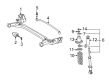
2003 Toyota Matrix Coil Spring, Rear
Part Number: 48231-AB010$76.30 MSRP: $107.10You Save: $30.80 (29%)Ships in 1-3 Business DaysProduct Specifications- Other Name: Spring, Coil, Rear; Coil Spring, Rear; Coil Spring Kit Rear; Coil Spring Set; Coil Springs; Spring; Spring, Coil, Rear Passenger Side; Spring, Coil, Rear Driver Side
- Position: Rear
- Item Weight: 3.60 Pounds
- Item Dimensions: 17.3 x 10.7 x 5.7 inches
- Condition: New
- Fitment Type: Direct Replacement
- SKU: 48231-AB010
- Warranty: This genuine part is guaranteed by Toyota's factory warranty.


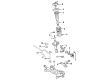
2003 Toyota Matrix Coil Spring, Front
Part Number: 48131-AB060$72.39 MSRP: $101.62You Save: $29.23 (29%)Ships in 1-3 Business DaysProduct Specifications- Other Name: Spring, Coil, Front; Coil Spring, Front; Coil Springs; Spring; Spring, Front Coil, Passenger Side; Spring, Front Coil, Driver Side
- Manufacturer Note: L=309.5
- Position: Front
- Item Weight: 4.60 Pounds
- Item Dimensions: 16.2 x 7.0 x 5.7 inches
- Condition: New
- Fitment Type: Direct Replacement
- SKU: 48131-AB060
- Warranty: This genuine part is guaranteed by Toyota's factory warranty.

2003 Toyota Matrix Coil Spring, Front
Part Number: 48135-02060$90.94 MSRP: $127.64You Save: $36.70 (29%)Ships in 1-3 Business DaysProduct Specifications- Other Name: Spring, Coil, Front; Coil Spring, Front; Coil Springs; Spring; Spring, Front Coil, Passenger Side; Spring, Front Coil, Driver Side
- Manufacturer Note: L=333.0
- Position: Front
- Item Weight: 4.70 Pounds
- Item Dimensions: 15.5 x 6.9 x 5.8 inches
- Condition: New
- Fitment Type: Direct Replacement
- SKU: 48135-02060
- Warranty: This genuine part is guaranteed by Toyota's factory warranty.

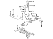
2003 Toyota Matrix Coil Spring, Rear
Part Number: 48231-02330$82.19 MSRP: $115.36You Save: $33.17 (29%)Ships in 1-3 Business DaysProduct Specifications- Other Name: Spring, Coil, Rear; Coil Spring, Rear; Coil Spring Kit Rear; Coil Spring Set; Coil Springs; Spring; Spring, Coil, Rear Passenger Side; Spring, Coil, Rear Driver Side
- Position: Rear
- Item Weight: 4.40 Pounds
- Item Dimensions: 17.3 x 10.7 x 5.6 inches
- Condition: New
- Fitment Type: Direct Replacement
- SKU: 48231-02330
- Warranty: This genuine part is guaranteed by Toyota's factory warranty.
2003 Toyota Matrix Coil Spring, Front
Part Number: 48131-AB090$69.48 MSRP: $97.52You Save: $28.04 (29%)Ships in 1-3 Business DaysProduct Specifications- Other Name: Spring, Coil, Front; Coil Springs; Spring; Spring, Front Coil, Passenger Side; Spring, Front Coil, Driver Side
- Position: Front
- Item Weight: 7.30 Pounds
- Item Dimensions: 15.9 x 6.9 x 6.0 inches
- Condition: New
- Fitment Type: Direct Replacement
- SKU: 48131-AB090
- Warranty: This genuine part is guaranteed by Toyota's factory warranty.
2003 Toyota Matrix Coil Spring, Front
Part Number: 48131-AB050$70.14 MSRP: $98.46You Save: $28.32 (29%)Ships in 1-3 Business DaysProduct Specifications- Other Name: Spring, Coil, Front; Coil Spring, Front; Coil Springs; Spring; Spring, Front Coil, Passenger Side; Spring, Front Coil, Driver Side
- Manufacturer Note: L=304.0
- Position: Front
- Item Weight: 7.10 Pounds
- Item Dimensions: 16.2 x 7.0 x 6.0 inches
- Condition: New
- Fitment Type: Direct Replacement
- SKU: 48131-AB050
- Warranty: This genuine part is guaranteed by Toyota's factory warranty.
2003 Toyota Matrix Coil Springs
Looking for affordable OEM 2003 Toyota Matrix Coil Springs? Explore our comprehensive catalogue of genuine 2003 Toyota Matrix Coil Springs. All our parts are covered by the manufacturer's warranty. Plus, our straightforward return policy and speedy delivery service ensure an unparalleled shopping experience. We look forward to your visit!
2003 Toyota Matrix Coil Springs Parts Q&A
- Q: How to overhaul the coil springs on 2003 Toyota Matrix?A: Begin coil spring overhaul by detaching the front wheel followed by disconnection of the front stabilizer link assembly LH by removing its nut while using a hexagon (6 mm) wrench to stabilize the stud when the ball joint rotates with the nut. The next step requires disconnecting the front flexible hose through bolt removal to separate both front flexible hose No. 1 and speed sensor front LH when using ABS or front flexible hose without ABS only. You should remove the front shock absorber with coil spring by detaching its lower side bolts and nuts and upper side nuts from the shock absorber assembly front LH while securing the bolt from rotating during nut loosening procedures. Install two nuts as well as a bolt to the lower shock absorber bracket for fixing it in a vise. LH side front suspension support dust cover should be removed before compressing the front coil spring LH with Special Service Tool: 09727-30021. The tool must be used without an impact wrench to prevent damage. The front coil spring seat upper LH requires Special Service Tool: 09729-22031 to hold it while you remove the nut and take out front suspension support sub-assembly LH and its dust seal and upper LH seat, insulator, spring, bumper, and lower insulator. Inspection of the shock absorber assembly front LH requires compressing and extending the shock absorber rod before replacing it if abnormal resistance or unusual sounds are detected during testing. The installation process for shock absorber assembly front LH begins by placing the front coil spring insulator lower LH onto the shock absorber assembly then adding the front spring bumper LH onto the shock absorber piston rod. Use the specified tool to compress the front coil spring LH before installing it properly onto the shock absorber assembly at the correct position with the spring lower seat gap. Each step in this installation requires beginning with the front coil spring insulator upper LH, then adding the front coil spring seat upper LH with its mark pointing outward followed by the front suspension support LH dust seal alongside the front suspension support sub-assembly LH. Secure the front coil spring seat upper LH with a newly installed nut through Special Service Tool: 09729-22031 before tightening it to 47 Nm (479 kgf-cm, 35 ft. lbs.) then discard the tool. Put the front suspension support dust cover LH in position before applying MP grease No.2 to the suspension support sub-assembly LH but avoid spreading it on the rubber surface of the upper support. To assemble the shock absorber with its coil spring install two bolts along with three nuts while rotating the bolt when torquing the nut to 39 Nm (398 kgf-cm, 29 ft. lbs.) then 220 Nm (2,243 kgf-cm, 162 ft. lbs.). For vehicles equipped with ABS use the speed sensor front LH in combination with its bolt and torque it to 29 Nm (296 kgf-cm, 21 ft. lbs.) while vehicles without ABS only need the front flexible hose and normal torque specifications of 29 Nm (296 kgf-cm, 21 ft. lbs.). Fasten the front stabilizer link assembly LH with its nut and tighten it to 74 Nm (755 kgf-cm, 55 ft. lbs.). Maintain grip on the stud with a hexagon wrench (6 mm) during installation when the ball joint rotates relative to the nut. Position the front wheel before tightening it to 103 Nm (1,050 kgf-cm, 76 ft. lbs.) while performing a front wheel alignment check. Before discharging the shock absorber gas inside the cylinder of the front LH shock absorber assembly fully extend the piston rod and drill a small hole while observing safety precautions against flying chips to ensure the colorless and odorless non-poisonous substance escapes safely.
Related 2003 Toyota Matrix Parts
 2003 Toyota Matrix Ball Joint
 2003 Toyota Matrix Sway Bar Link
 2003 Toyota Matrix Coil Spring Insulator
 2003 Toyota Matrix Control Arm Bolt
 2003 Toyota Matrix Control Arm Bracket
 2003 Toyota Matrix Lateral Link
 2003 Toyota Matrix Shock and Strut Boot
 2003 Toyota Matrix Steering Knuckle
 2003 Toyota Matrix Strut Housing
 2003 Toyota Matrix Suspension Strut Rod
 2003 Toyota Matrix Sway Bar Bushing
 2003 Toyota Matrix Trailing Arm Bushing