×
ToyotaParts- Hello
- Login or Register
- Quick Links
- Live Chat
- Track Order
- Parts Availability
- RMA
- Help Center
- Contact Us
- Shop for
- Toyota Parts
- Scion Parts
My Garage
My Account
Cart
OEM Scion Drive Belt
Serpentine Belt- Select Vehicle by Model
- Select Vehicle by VIN
Select Vehicle by Model
orMake
Model
Year
Select Vehicle by VIN
For the most accurate results, select vehicle by your VIN (Vehicle Identification Number).
16 Drive Belts found


Scion Serpentine Belt Part Number: 90916-A2021
$25.56 MSRP: $35.58You Save: $10.02 (29%)Ships in 1-3 Business DaysProduct Specifications- Other Name: Belt, V-Ribbed; Serpentine Belt Drive Kit; Accessory Drive Belt; Drive Belt; V-Belt; Belt, V(For Fan & Alternator)
- Replaces: 90916-02667


Scion Serpentine Belt Part Number: 90916-02705
$22.45 MSRP: $31.25You Save: $8.80 (29%)Ships in 1-3 Business DaysProduct Specifications- Other Name: Belt, V-Ribbed; Serpentine Belt Drive Kit; Accessory Drive Belt; Drive Belt; V-Belt; Alternator Belt; Belt, V(For Fan & Alternator)
- Manufacturer Note: AIR CONDITIONER COMPRESSOR-WITHOUT
- Replaces: 90916-02556, 90916-02543


Scion Serpentine Belt Part Number: 90916-02664
$34.28 MSRP: $47.72You Save: $13.44 (29%)Ships in 1-2 Business DaysProduct Specifications- Other Name: Belt, V-Ribbed; Serpentine Belt Drive Kit; Accessory Drive Belt; Drive Belt; V-Belt; Belt, V(For Fan & Alternator)
- Replaces: 99366-K1230


Scion Serpentine Belt Part Number: 90916-02652
$39.90 MSRP: $55.53You Save: $15.63 (29%)Ships in 1-3 Business DaysProduct Specifications- Other Name: Belt, V-Ribbed; Serpentine Belt Drive Kit; Accessory Drive Belt; Drive Belt; V-Belt; Belt, V(For Fan & Alternator)
- Manufacturer Note: 2AZ-FE,*195,BANDO


Scion Serpentine Belt Part Number: 90916-A2005
$37.39 MSRP: $52.04You Save: $14.65 (29%)Ships in 1-3 Business DaysProduct Specifications- Other Name: Belt, V-Ribbed; Serpentine Belt Drive Kit; Accessory Drive Belt; Drive Belt; V-Belt; Belt, V(For Fan & Alternator)
- Manufacturer Note: (L)
- Replaces: 90916-02599


Scion Power Steering Belt Part Number: 90916-02711
$11.46 MSRP: $15.95You Save: $4.49 (29%)Ships in 1-2 Business DaysProduct Specifications- Other Name: Belt, V-Ribbed; Accessory Drive Belt; Serpentine Belt Drive Kit; Serpentine Belt; Drive Belt; V-Belt
- Replaces: 90916-02576, 90916-02575, 99363-30850


Scion Serpentine Belt Part Number: 90916-02668
$33.69 MSRP: $46.89You Save: $13.20 (29%)Ships in 1-3 Business DaysProduct Specifications- Other Name: Belt, V-Ribbed; Serpentine Belt Drive Kit; Accessory Drive Belt; Drive Belt; V-Belt; Belt, V(For Fan & Alternator)
- Manufacturer Note: MITSUBOSHI


Scion A/C Belt Part Number: 90916-02670
$15.88 MSRP: $22.11You Save: $6.23 (29%)Ships in 1 Business DayProduct Specifications- Other Name: Belt, V-Ribbed; Serpentine Belt Drive Kit; Accessory Drive Belt; Serpentine Belt; Drive Belt; V-Belt; Belt, V (Cooler Compressor To Crankshaft Pulley)
- Manufacturer Note: L=800


Scion Water Pump Belt Part Number: 90118-WB464
$20.26 MSRP: $28.19You Save: $7.93 (29%)Ships in 1 Business DayProduct Specifications- Other Name: Belt'V', Water Pump; Accessory Drive Belt; Serpentine Belt Drive Kit; Serpentine Belt; V-Belt; Belt, V(For Water Pump & Crankshaft Pulley); Drive Belt


Scion Serpentine Belt Part Number: 90916-02682
$23.17 MSRP: $32.25You Save: $9.08 (29%)Ships in 1 Business DayProduct Specifications- Other Name: Belt, V-Ribbed; Serpentine Belt Drive Kit; Accessory Drive Belt; Drive Belt; V-Belt; Belt, V(For Fan & Alternator)
- Manufacturer Note: COLD AREA SPEC(FOR NORTH AMERICA)


Scion Serpentine Belt Part Number: 90916-02609
$34.76 MSRP: $48.39You Save: $13.63 (29%)Ships in 1-3 Business DaysProduct Specifications- Other Name: Belt, V-Ribbed; Serpentine Belt Drive Kit; Drive Belt; V-Belt; Belt, V(For Fan & Alternator)


Scion Serpentine Belt Part Number: 90916-02600
$54.24 MSRP: $75.50You Save: $21.26 (29%)Ships in 1-2 Business DaysProduct Specifications- Other Name: Belt, V-Ribbed; Serpentine Belt Drive Kit; Accessory Drive Belt; Drive Belt; V-Belt; Belt, V(For Fan & Alternator)
- Manufacturer Note: BANDO

Scion Serpentine Belt Part Number: 90916-02601
$56.75 MSRP: $78.99You Save: $22.24 (29%)Ships in 1-2 Business DaysProduct Specifications- Other Name: Belt, V-Ribbed; Serpentine Belt Drive Kit; Accessory Drive Belt; Drive Belt; V-Belt; Belt, V(For Fan & Alternator)
- Manufacturer Note: MITSUBOSHI


Scion Serpentine Belt Part Number: SU003-02202
$31.39 MSRP: $40.64You Save: $9.25 (23%)Ships in 1-3 Business DaysProduct Specifications- Other Name: V Belt-21X4X2070; Serpentine Belt Drive Kit; Accessory Drive Belt; Drive Belt; V-Belt; Belt, V(For Fan & Alternator)


Scion Serpentine Belt Part Number: 90916-02681
$23.05 MSRP: $32.09You Save: $9.04 (29%)Ships in 1-3 Business DaysProduct Specifications- Other Name: Belt, V-Ribbed; Serpentine Belt Drive Kit; Accessory Drive Belt; Drive Belt; V-Belt; Belt, V(For Fan & Alternator)

Scion Serpentine Belt Part Number: 90118-WBA55
$30.46 MSRP: $42.39You Save: $11.93 (29%)Product Specifications- Other Name: Belt'V', Alternator.& A; Serpentine Belt Drive Kit; Drive Belt; V-Belt; Alternator Belt; Belt, V(For Fan & Alternator)
- Replaces: 90118-WB455
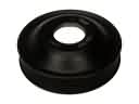
Scion Drive Belt
OEM parts deliver unmatched quality you can rely on. They pass extensive quality control inspections. Scion produces them to the official factory specifications. This process helps prevent defects and imperfections. So you can get exceptional lifespan and a flawless fit. Need new OEM Scion Drive Belt? You'll love our wide selection of genuine options. Shop in minutes and skip the hunt. Our prices are unbeatable, you'll save time and money. It's easy to shop and find the right piece. Our committed customer service team gives professional help from start to finish. Every part includes a manufacturer's warranty. We ship quickly, your parts will arrive fast at your door.
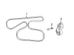
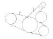
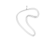
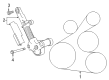
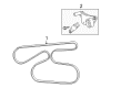
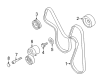
The Scion Drive Belt ensures that all the components are rotating in tandem, reducing wastage and increasing daily driving assurance. The brand also caught the eye by abandoning overweight trim descriptions and selling nimble compacts in loud colors that customers could customize without breaking their wallets. Scion treated showrooms as experimentation, releasing small batches under Release Series, which quickly sold out and made first-time drivers into fanatics. Scion created a virtual Scion City on the internet, which allowed shoppers to explore identity just as they did horsepower. Before the year 2016, Scion sold more than 1,000,000 vehicles, but its simple pricing and innovative approach resonate in the current cars on the driveway. Drive Belt routes transfer the engine torque via pulleys to the alternator, water pump, and A/C compressor, and thus in case its ribs cut cleanly, the battery remains charged, the coolant circulates, the cabin cool, and the horsepower remains in the same place. Drive Belt has the ability to pass 100,000 miles; however, glazing or frays will complain well before components fail to do so. Drive Belt is based on hard rubber material that clings but does not slip, is resistant to heat and sprays up on the road, and provides steady power without the continuous hood noise.
Scion Drive Belt Parts and Q&A
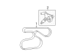
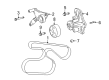
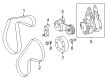
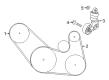
- Q: How to install the fan and generator Drive Belt on Scion tC?A:Users can install the 2AZ-FE engine fan and generator V belt through the use of Special Service Tool: 09249-63010 to rotate the V-ribbed belt tensioner arm clockwise first before placing the belt. All uses of Special Service Tool and other tools should maintain proper alignment while in operation. Retrofit the tensioner while turning it clockwise throughout 3 seconds of direct motion before applying any sharp force. The restraint of the tensioner should be achieved without any extra force on the mechanism. The front fender apron seal RH needs to be installed before finishing the task.
- Q: How to remove the drive belt on Scion xB?A:The removal process for the drive belt from 2AZ-FE engine begins with the rear engine under cover removal from its right-hand side position. Service Tool items 09216-42010 and 09216-04010 combined with a 19 mm socket wrench enable belt tensioner arm loosening clockwise before fan and generator V belt are removed. Under normal use conditions it is essential to keep the Special Service Tool and its accompanying tools properly lined up. Slowing down your rotation speed to at least 3 seconds is essential when turning the tensioner clockwise. Speed up the force application. The tensioner should be treated with minimal additional force once its full retraction is accomplished.