×
ToyotaParts- Hello
- Login or Register
- Quick Links
- Live Chat
- Track Order
- Parts Availability
- RMA
- Help Center
- Contact Us
- Shop for
- Toyota Parts
- Scion Parts
My Garage
My Account
Cart
OEM 2007 Toyota RAV4 Axle Shaft
Car Axle Shaft- Select Vehicle by Model
- Select Vehicle by VIN
Select Vehicle by Model
orMake
Model
Year
Select Vehicle by VIN
For the most accurate results, select vehicle by your VIN (Vehicle Identification Number).
12 Axle Shafts found


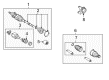
2007 Toyota RAV4 Axle Assembly, Driver Side
Part Number: 43420-0R030$298.66 MSRP: $452.96You Save: $154.30 (35%)Ships in 1-3 Business DaysProduct Specifications- Other Name: Shaft Assembly, Front Drive; CV Axle Assembly, Front Left; GSP Cv Axle; Axle Shaft; Shaft Assembly, Front Drive, Driver Side; CV Axle Assembly
- Position: Driver Side
- Replaces: 43420-42170
- Part Name Code: 43420
- Item Weight: 5.70 Pounds
- Item Dimensions: 6.7 x 4.7 x 4.7 inches
- Condition: New
- Fitment Type: Direct Replacement
- SKU: 43420-0R030
- Warranty: This genuine part is guaranteed by Toyota's factory warranty.


2007 Toyota RAV4 Axle Assembly, Driver Side
Part Number: 43420-0R010$298.66 MSRP: $452.96You Save: $154.30 (35%)Ships in 1-3 Business DaysProduct Specifications- Other Name: Shaft Assembly, Front Drive; CV Axle Assembly, Front Left; GSP Cv Axle; Axle Shaft; Shaft Assembly, Front Drive, Driver Side; CV Axle Assembly
- Position: Driver Side
- Part Name Code: 43420
- Item Weight: 6.10 Pounds
- Item Dimensions: 6.5 x 4.7 x 4.8 inches
- Condition: New
- Fitment Type: Direct Replacement
- SKU: 43420-0R010
- Warranty: This genuine part is guaranteed by Toyota's factory warranty.


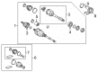
2007 Toyota RAV4 Axle Assembly, Passenger Side
Part Number: 43410-0R030$373.52 MSRP: $573.92You Save: $200.40 (35%)Product Specifications- Other Name: Shaft Assembly, Front Drive; CV Axle Assembly, Front Right; GSP Cv Axle; Axle Shaft; Shaft Assembly, Front Drive, Passenger Side; CV Axle Assembly
- Position: Passenger Side
- Replaces: 43410-42170
- Part Name Code: 43410
- Item Weight: 6.00 Pounds
- Item Dimensions: 6.8 x 4.8 x 4.7 inches
- Condition: New
- Fitment Type: Direct Replacement
- SKU: 43410-0R030
- Warranty: This genuine part is guaranteed by Toyota's factory warranty.

2007 Toyota RAV4 Shaft & Joint Assembly, Rear
Part Number: 42370-49285$245.80 MSRP: $350.95You Save: $105.15 (30%)Ships in 1-3 Business DaysProduct Specifications- Other Name: Shaft Set, Rear Drive; Axle Shaft; CV Joint; Outer Joint Assembly; Rear Drive Outboard Joint, Passenger & Driver Side.
- Position: Rear
- Item Weight: 14.10 Pounds
- Item Dimensions: 33.7 x 6.4 x 5.9 inches
- Condition: New
- Fitment Type: Direct Replacement
- SKU: 42370-49285
- Warranty: This genuine part is guaranteed by Toyota's factory warranty.

2007 Toyota RAV4 Outer Joint Assembly, Driver Side
Part Number: 43470-49675$232.71 MSRP: $332.25You Save: $99.54 (30%)Ships in 1-3 Business DaysProduct Specifications- Other Name: Shaft Set, Outboard; CV Joint
- Position: Driver Side
- Item Weight: 4.60 Pounds
- Condition: New
- SKU: 43470-49675
- Warranty: This genuine part is guaranteed by Toyota's factory warranty.
2007 Toyota RAV4 Outer Joint Assembly, Driver Side
Part Number: 43470-49635$232.71 MSRP: $332.25You Save: $99.54 (30%)Ships in 1-3 Business DaysProduct Specifications- Other Name: Shaft Set, Outboard; CV Joint
- Position: Driver Side
- Item Weight: 5.70 Pounds
- Item Dimensions: 6.5 x 4.6 x 4.7 inches
- Condition: New
- SKU: 43470-49635
- Warranty: This genuine part is guaranteed by Toyota's factory warranty.


2007 Toyota RAV4 Axle Assembly, Passenger Side
Part Number: 43410-0R040$459.32 MSRP: $673.14You Save: $213.82 (32%)Ships in 1-3 Business DaysProduct Specifications- Other Name: Shaft Assembly, Front Drive; CV Axle Assembly, Front Right; GSP Cv Axle; Axle Shaft; Shaft Assembly, Front Drive, Passenger Side; CV Axle Assembly
- Position: Passenger Side
- Part Name Code: 43410
- Item Weight: 15.30 Pounds
- Item Dimensions: 29.8 x 7.6 x 6.4 inches
- Condition: New
- Fitment Type: Direct Replacement
- SKU: 43410-0R040
- Warranty: This genuine part is guaranteed by Toyota's factory warranty.
2007 Toyota RAV4 Axle Assembly, Passenger Side
Part Number: 43410-0R011$527.92 MSRP: $773.67You Save: $245.75 (32%)Ships in 1-3 Business DaysProduct Specifications- Other Name: Shaft Assembly, Front Drive; CV Axle Assembly, Front Right; GSP Cv Axle; Axle Shaft; Shaft Assembly, Front Drive, Passenger Side; CV Axle Assembly
- Position: Passenger Side
- Replaces: 43410-0R010
- Part Name Code: 43410
- Condition: New
- Fitment Type: Direct Replacement
- SKU: 43410-0R011
- Warranty: This genuine part is guaranteed by Toyota's factory warranty.

2007 Toyota RAV4 Axle Assembly, Front Driver Side
Part Number: 43420-0R042$438.21 MSRP: $642.20You Save: $203.99 (32%)Ships in 1-3 Business DaysProduct Specifications- Other Name: Shaft Assembly, Front Drive; CV Axle Assembly, Front Left; CV Axle Assembly; GSP Cv Axle; Axle Shaft
- Position: Front Driver Side
- Replaces: 43420-0R041, 43420-0R040
- Condition: New
- SKU: 43420-0R042
- Warranty: This genuine part is guaranteed by Toyota's factory warranty.
2007 Toyota RAV4 Axle Assembly, Driver Side
Part Number: 43420-0R021$360.35 MSRP: $528.10You Save: $167.75 (32%)Ships in 1-3 Business DaysProduct Specifications- Other Name: Shaft Assembly, Front Drive; CV Axle Assembly; GSP Cv Axle; Axle Shaft; Shaft Assembly, Front Drive, Driver Side
- Position: Driver Side
- Replaces: 43420-0R020, 43420-42210
- Part Name Code: 43420
- Item Weight: 14.60 Pounds
- Item Dimensions: 29.5 x 7.5 x 6.4 inches
- Condition: New
- Fitment Type: Direct Replacement
- SKU: 43420-0R021
- Warranty: This genuine part is guaranteed by Toyota's factory warranty.

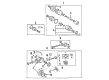
2007 Toyota RAV4 Axle Assembly, Rear
Part Number: 42330-42050$380.89 MSRP: $558.21You Save: $177.32 (32%)Ships in 1-3 Business DaysProduct Specifications- Other Name: Shaft Assembly, Rear Drive; CV Axle Assembly, Rear, Rear Left, Rear Right; GSP Cv Axle; Axle Shaft; CV Joint; Shaft & Joint Assembly; Rear Drive CV Axle Assembly, Passenger & Driver Side.
- Position: Rear
- Item Weight: 12.00 Pounds
- Item Dimensions: 25.2 x 4.1 x 4.1 inches
- Condition: New
- Fitment Type: Direct Replacement
- SKU: 42330-42050
- Warranty: This genuine part is guaranteed by Toyota's factory warranty.
- Product Specifications
- Other Name: Shaft Assembly, Front Drive; CV Axle Assembly, Front Right; Axle Shaft; Shaft Assembly, Front Drive, Passenger Side
- Position: Passenger Side
- Replaces: 43410-0R020
- Part Name Code: 43410
- Item Weight: 16.60 Pounds
- Condition: New
- Fitment Type: Direct Replacement
- SKU: 43410-0R021
- Warranty: This genuine part is guaranteed by Toyota's factory warranty.
2007 Toyota RAV4 Axle Shaft
Looking for affordable OEM 2007 Toyota RAV4 Axle Shaft? Explore our comprehensive catalogue of genuine 2007 Toyota RAV4 Axle Shaft. All our parts are covered by the manufacturer's warranty. Plus, our straightforward return policy and speedy delivery service ensure an unparalleled shopping experience. We look forward to your visit!
2007 Toyota RAV4 Axle Shaft Parts Q&A
- Q: How to service and repair the axle shaft assembly on 2007 Toyota RAV4?A: Start the front drive shaft assembly servicing and repair operation by disconnecting the front wheel followed by automatic transaxle fluid drainage and removing the front axle hub nut. Service technicians should detach the front speed sensors from both left and right sides then proceed with uninstalling front disc brake cylinder assemblies on both sides. Service on the front drive shaft begins by removing front stabilizer link assemblies while disconnecting front suspension lower No. 1 arm sub-assemblies and steering knuckles with their axle hubs on both sides. Director the drive shaft marking process without damaging either component. Use Special Service Tool: 09520-01010, 09520-24010 (09520-32040) on the left side and remove the two bolts on the right side to disconnect the tie rod ends before removing the front drive shaft assemblies. The front axle assembly needs Special Service Tool: 09608-16042 (09608-02021, 09608-02041) for fixation when required. Perform disassembly operations by first removing the inboard joint boot clamps, the inboard joint boot and the front drive inboard joint assemblies from both sides while marking each joint before discarding any old grease. Remove the front drive shaft damper clamps and dampers then proceed with unclamping and removing outboard joint boots and drive shaft hole snap rings and dust covers by using Special Service Tool: 09950-00020. Drive the process by putting dust covers into place on the drive shaft bearing case followed by checking depth and alignment before securing outboard joint boots through clamps with grease insertion. Before installation of front drive shaft assemblies the splines must receive gear oil application followed by tightening bearing bracket bolts to 63.7 Nm (650 kgf-cm, 47 ft. lbs.). Reassemble the vehicle by reconnecting steering knuckles, front suspension lower arms, stabilizer links, tie rod ends and front speed sensors and axle hub nut as the last step before reinstallation of the front wheel with 1,050 kgf-cm torque. Check for fluid leaks and perform automatic transaxle fluid addition then verify the front wheel alignment while inspecting for measuring and adjusting accordingly.
Related 2007 Toyota RAV4 Parts
 2007 Toyota RAV4 CV Joint
 2007 Toyota RAV4 Control Arm
 2007 Toyota RAV4 Sway Bar Bushing
 2007 Toyota RAV4 Bump Stop
 2007 Toyota RAV4 CV Boot
 2007 Toyota RAV4 Coil Spring Insulator
 2007 Toyota RAV4 Coil Springs
 2007 Toyota RAV4 Differential Mount
 2007 Toyota RAV4 Rear Crossmember
 2007 Toyota RAV4 Shock Absorber
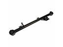 2007 Toyota RAV4 Trailing Arm
 2007 Toyota RAV4 Wheel Seal