×
ToyotaParts- Hello
- Login or Register
- Quick Links
- Live Chat
- Track Order
- Parts Availability
- RMA
- Help Center
- Contact Us
- Shop for
- Toyota Parts
- Scion Parts
My Garage
My Account
Cart
OEM 2008 Toyota RAV4 Axle Shaft
Car Axle Shaft- Select Vehicle by Model
- Select Vehicle by VIN
Select Vehicle by Model
orMake
Model
Year
Select Vehicle by VIN
For the most accurate results, select vehicle by your VIN (Vehicle Identification Number).
12 Axle Shafts found


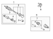
2008 Toyota RAV4 Axle Assembly, Driver Side
Part Number: 43420-0R030$298.66 MSRP: $452.96You Save: $154.30 (35%)Ships in 1-3 Business DaysProduct Specifications- Other Name: Shaft Assembly, Front Drive; CV Axle Assembly, Front Left; GSP Cv Axle; Axle Shaft; Shaft Assembly, Front Drive, Driver Side; CV Axle Assembly
- Position: Driver Side
- Replaces: 43420-42170
- Part Name Code: 43420
- Item Weight: 5.70 Pounds
- Item Dimensions: 6.7 x 4.7 x 4.7 inches
- Condition: New
- Fitment Type: Direct Replacement
- SKU: 43420-0R030
- Warranty: This genuine part is guaranteed by Toyota's factory warranty.


2008 Toyota RAV4 Axle Assembly, Driver Side
Part Number: 43420-0R010$298.66 MSRP: $452.96You Save: $154.30 (35%)Ships in 1-3 Business DaysProduct Specifications- Other Name: Shaft Assembly, Front Drive; CV Axle Assembly, Front Left; GSP Cv Axle; Axle Shaft; Shaft Assembly, Front Drive, Driver Side; CV Axle Assembly
- Position: Driver Side
- Part Name Code: 43420
- Item Weight: 6.10 Pounds
- Item Dimensions: 6.5 x 4.7 x 4.8 inches
- Condition: New
- Fitment Type: Direct Replacement
- SKU: 43420-0R010
- Warranty: This genuine part is guaranteed by Toyota's factory warranty.


2008 Toyota RAV4 Axle Assembly, Passenger Side
Part Number: 43410-0R030$373.52 MSRP: $573.92You Save: $200.40 (35%)Product Specifications- Other Name: Shaft Assembly, Front Drive; CV Axle Assembly, Front Right; GSP Cv Axle; Axle Shaft; Shaft Assembly, Front Drive, Passenger Side; CV Axle Assembly
- Position: Passenger Side
- Replaces: 43410-42170
- Part Name Code: 43410
- Item Weight: 6.00 Pounds
- Item Dimensions: 6.8 x 4.8 x 4.7 inches
- Condition: New
- Fitment Type: Direct Replacement
- SKU: 43410-0R030
- Warranty: This genuine part is guaranteed by Toyota's factory warranty.

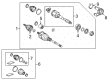
2008 Toyota RAV4 Shaft & Joint Assembly, Rear
Part Number: 42370-49285$245.80 MSRP: $350.95You Save: $105.15 (30%)Ships in 1-3 Business DaysProduct Specifications- Other Name: Shaft Set, Rear Drive; Axle Shaft; CV Joint; Outer Joint Assembly; Rear Drive Outboard Joint, Passenger & Driver Side.
- Position: Rear
- Item Weight: 14.10 Pounds
- Item Dimensions: 33.7 x 6.4 x 5.9 inches
- Condition: New
- Fitment Type: Direct Replacement
- SKU: 42370-49285
- Warranty: This genuine part is guaranteed by Toyota's factory warranty.

2008 Toyota RAV4 Outer Joint Assembly, Driver Side
Part Number: 43470-49675$232.71 MSRP: $332.25You Save: $99.54 (30%)Ships in 1-3 Business DaysProduct Specifications- Other Name: Shaft Set, Outboard; CV Joint
- Position: Driver Side
- Item Weight: 4.60 Pounds
- Condition: New
- SKU: 43470-49675
- Warranty: This genuine part is guaranteed by Toyota's factory warranty.
2008 Toyota RAV4 Outer Joint Assembly, Driver Side
Part Number: 43470-49635$232.71 MSRP: $332.25You Save: $99.54 (30%)Ships in 1-3 Business DaysProduct Specifications- Other Name: Shaft Set, Outboard; CV Joint
- Position: Driver Side
- Item Weight: 5.70 Pounds
- Item Dimensions: 6.5 x 4.6 x 4.7 inches
- Condition: New
- SKU: 43470-49635
- Warranty: This genuine part is guaranteed by Toyota's factory warranty.


2008 Toyota RAV4 Axle Assembly, Passenger Side
Part Number: 43410-0R040$459.32 MSRP: $673.14You Save: $213.82 (32%)Ships in 1-3 Business DaysProduct Specifications- Other Name: Shaft Assembly, Front Drive; CV Axle Assembly, Front Right; GSP Cv Axle; Axle Shaft; Shaft Assembly, Front Drive, Passenger Side; CV Axle Assembly
- Position: Passenger Side
- Part Name Code: 43410
- Item Weight: 15.30 Pounds
- Item Dimensions: 29.8 x 7.6 x 6.4 inches
- Condition: New
- Fitment Type: Direct Replacement
- SKU: 43410-0R040
- Warranty: This genuine part is guaranteed by Toyota's factory warranty.
2008 Toyota RAV4 Axle Assembly, Passenger Side
Part Number: 43410-0R011$527.92 MSRP: $773.67You Save: $245.75 (32%)Ships in 1-3 Business DaysProduct Specifications- Other Name: Shaft Assembly, Front Drive; CV Axle Assembly, Front Right; GSP Cv Axle; Axle Shaft; Shaft Assembly, Front Drive, Passenger Side; CV Axle Assembly
- Position: Passenger Side
- Replaces: 43410-0R010
- Part Name Code: 43410
- Condition: New
- Fitment Type: Direct Replacement
- SKU: 43410-0R011
- Warranty: This genuine part is guaranteed by Toyota's factory warranty.

2008 Toyota RAV4 Axle Assembly, Front Driver Side
Part Number: 43420-0R042$438.21 MSRP: $642.20You Save: $203.99 (32%)Ships in 1-3 Business DaysProduct Specifications- Other Name: Shaft Assembly, Front Drive; CV Axle Assembly, Front Left; CV Axle Assembly; GSP Cv Axle; Axle Shaft
- Position: Front Driver Side
- Replaces: 43420-0R041, 43420-0R040
- Condition: New
- SKU: 43420-0R042
- Warranty: This genuine part is guaranteed by Toyota's factory warranty.
2008 Toyota RAV4 Axle Assembly, Driver Side
Part Number: 43420-0R021$360.35 MSRP: $528.10You Save: $167.75 (32%)Ships in 1-3 Business DaysProduct Specifications- Other Name: Shaft Assembly, Front Drive; CV Axle Assembly; GSP Cv Axle; Axle Shaft; Shaft Assembly, Front Drive, Driver Side
- Position: Driver Side
- Replaces: 43420-0R020, 43420-42210
- Part Name Code: 43420
- Item Weight: 14.60 Pounds
- Item Dimensions: 29.5 x 7.5 x 6.4 inches
- Condition: New
- Fitment Type: Direct Replacement
- SKU: 43420-0R021
- Warranty: This genuine part is guaranteed by Toyota's factory warranty.

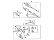
2008 Toyota RAV4 Axle Assembly, Rear
Part Number: 42330-42050$380.89 MSRP: $558.21You Save: $177.32 (32%)Ships in 1-3 Business DaysProduct Specifications- Other Name: Shaft Assembly, Rear Drive; CV Axle Assembly, Rear, Rear Left, Rear Right; GSP Cv Axle; Axle Shaft; CV Joint; Shaft & Joint Assembly; Rear Drive CV Axle Assembly, Passenger & Driver Side.
- Position: Rear
- Item Weight: 12.00 Pounds
- Item Dimensions: 25.2 x 4.1 x 4.1 inches
- Condition: New
- Fitment Type: Direct Replacement
- SKU: 42330-42050
- Warranty: This genuine part is guaranteed by Toyota's factory warranty.
- Product Specifications
- Other Name: Shaft Assembly, Front Drive; CV Axle Assembly, Front Right; Axle Shaft; Shaft Assembly, Front Drive, Passenger Side
- Position: Passenger Side
- Replaces: 43410-0R020
- Part Name Code: 43410
- Item Weight: 16.60 Pounds
- Condition: New
- Fitment Type: Direct Replacement
- SKU: 43410-0R021
- Warranty: This genuine part is guaranteed by Toyota's factory warranty.
2008 Toyota RAV4 Axle Shaft
Looking for affordable OEM 2008 Toyota RAV4 Axle Shaft? Explore our comprehensive catalogue of genuine 2008 Toyota RAV4 Axle Shaft. All our parts are covered by the manufacturer's warranty. Plus, our straightforward return policy and speedy delivery service ensure an unparalleled shopping experience. We look forward to your visit!
2008 Toyota RAV4 Axle Shaft Parts Q&A
- Q: How to disassemble the Axle Shaft assembly on 2008 Toyota RAV4?A: The procedure to disassemble the 2WD front drive shaft assembly starts with using a screwdriver on one touch types or needle-nose pliers on claw engagement types to remove the front axle inboard joint boot clamp. First remove the inboard joint boot and cleanse old grease from the inboard joint while carefully adding matchmarks to inboard and outboard joint shafts without actual punching. A snap ring expander allows you to remove the shaft snap ring after detaching the inboard joint from the outboard joint shaft. Use matchmarks to mark the outboard joint shaft and tripod joint and gently tap out the tripod joint by hammering a brass bar to avoid the rollers. You should perform identical procedures on the right-hand side. The front drive shaft damper can be detached by using a screwdriver or needle-nose pliers to remove the clamp followed by taking off the front drive shaft damper. After removing the outboard joint boot clamps the technician will free the outboard joint boot before cleaning old grease off the outboard joint assembly. With the help of a screwdriver remove the front drive shaft hole snap ring. Special Service Tool: 09950-00020 combined with a press will enable you to detach the dust cover from both left and right-hand sides but caution must be taken to prevent the inboard joint from falling. Use a screwdriver to detach the bearing case snap ring and press out the drive shaft bearing case from the right-hand side before the inboard joint can fall. Pressed out the bearing case snap ring using Special Service Tool: 09527-10011 after taking off the snap ring with a snap ring expander tool.
Related 2008 Toyota RAV4 Parts
 2008 Toyota RAV4 CV Joint
 2008 Toyota RAV4 Control Arm
 2008 Toyota RAV4 Sway Bar Bushing
 2008 Toyota RAV4 Bump Stop
 2008 Toyota RAV4 CV Boot
 2008 Toyota RAV4 Coil Spring Insulator
 2008 Toyota RAV4 Coil Springs
 2008 Toyota RAV4 Differential Mount
 2008 Toyota RAV4 Rear Crossmember
 2008 Toyota RAV4 Shock Absorber
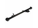 2008 Toyota RAV4 Trailing Arm
 2008 Toyota RAV4 Wheel Seal