×
ToyotaParts- Hello
- Login or Register
- Quick Links
- Live Chat
- Track Order
- Parts Availability
- RMA
- Help Center
- Contact Us
- Shop for
- Toyota Parts
- Scion Parts
My Garage
My Account
Cart
OEM 2006 Toyota 4Runner Control Arm
Suspension Arm- Select Vehicle by Model
- Select Vehicle by VIN
Select Vehicle by Model
orMake
Model
Year
Select Vehicle by VIN
For the most accurate results, select vehicle by your VIN (Vehicle Identification Number).
4 Control Arms found


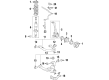
2006 Toyota 4Runner Arm Assembly, Front Suspension, Upper Driver Side
Part Number: 48630-60040$285.06 MSRP: $407.00You Save: $121.94 (30%)Product Specifications- Other Name: Arm Assembly, Suspension; Suspension Control Arm; Control Arm
- Position: Upper Driver Side
- Replaces: 48630-60020
- Part Name Code: 48630
- Item Weight: 6.30 Pounds
- Item Dimensions: 18.4 x 6.5 x 14.6 inches
- Condition: New
- Fitment Type: Direct Replacement
- SKU: 48630-60040
- Warranty: This genuine part is guaranteed by Toyota's factory warranty.

2006 Toyota 4Runner Upper Control Arm, Passenger Side
Part Number: 48610-60070$285.06 MSRP: $407.00You Save: $121.94 (30%)Product Specifications- Other Name: Arm Assembly, Suspension; Suspension Control Arm, Front Right Upper; Control Arm Assembly; Arm Assembly, Front Suspension Upper, Passenger Side; Suspension Control Arm; Control Arm
- Position: Passenger Side
- Replaces: 48610-60050
- Part Name Code: 48610
- Item Weight: 5.70 Pounds
- Item Dimensions: 18.3 x 6.8 x 14.9 inches
- Condition: New
- Fitment Type: Direct Replacement
- SKU: 48610-60070
- Warranty: This genuine part is guaranteed by Toyota's factory warranty.


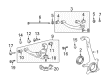
2006 Toyota 4Runner Lower Control Arm, Driver Side
Part Number: 48069-60010$341.34 MSRP: $500.24You Save: $158.90 (32%)Product Specifications- Other Name: Arm Sub-Assembly, Suspension; Suspension Control Arm, Front Left Lower; Control Arm Assembly; Arm Sub-Assembly, Front Suspension, Lower Driver Side; Suspension Control Arm; Control Arm
- Position: Lower Driver Side
- Part Name Code: 48069
- Item Weight: 42.40 Pounds
- Item Dimensions: 21.0 x 16.6 x 18.0 inches
- Condition: New
- Fitment Type: Direct Replacement
- SKU: 48069-60010
- Warranty: This genuine part is guaranteed by Toyota's factory warranty.

2006 Toyota 4Runner Arm Sub-Assembly, Front Suspension, Lower Passenger Side
Part Number: 48068-60010$340.46 MSRP: $486.10You Save: $145.64 (30%)Product Specifications- Other Name: Arm Sub-Assembly, Suspension; Suspension Control Arm; Control Arm
- Position: Passenger Side
- Part Name Code: 48068
- Item Weight: 43.20 Pounds
- Item Dimensions: 19.2 x 3.5 x 18.1 inches
- Condition: New
- Fitment Type: Direct Replacement
- SKU: 48068-60010
- Warranty: This genuine part is guaranteed by Toyota's factory warranty.
2006 Toyota 4Runner Control Arm
Looking for affordable OEM 2006 Toyota 4Runner Control Arm? Explore our comprehensive catalogue of genuine 2006 Toyota 4Runner Control Arm. All our parts are covered by the manufacturer's warranty. Plus, our straightforward return policy and speedy delivery service ensure an unparalleled shopping experience. We look forward to your visit!
2006 Toyota 4Runner Control Arm Parts Q&A
- Q: How to overhaul the Front Control Arm Sub-Assembly Lower No.1 LH on 2006 Toyota 4Runner?A: The first step for overhauling the Front Suspension Arm Sub-Assembly Lower No.1 LH requires removal of the front disc wheel. Professionals must inspect Front Suspension Arm Sub-Assembly Lower No.1 LH along with disc hub nuts attached when they use a dial indicator to measure 294 N (30 kgf, 66 lbs.) ball joint lower play. Excessive play greater than 0.5 mm (0.020 inch) requires replacement of the lower arm. Secondly the front shock absorber with coil spring requires removal of its bolt and nut followed by washer before separation from the suspension lower arm takes place. Separate the front lower ball joint attachment LH from the front axle by removing its 2 bolts before placing matchmarks on the camber adjust cam No.2 and toe adjust cam sub-assembly and extracting the nut along with the camber adjust cam No.2, camber adjust cam assembly, bolt, toe adjust cam sub-assembly, toe adjust plate No.2, and front suspension arm sub-assembly lower No.1 LH. Detach the front lower ball joint attachment LH by first removing its cotter pin and nut and secondly using Special Service Tool: 09628-00011. To remove front lower arm bush No.1 LH, first hammer and chisel the bushing flange diagonally before using Special Service Tool: 09632-36010, 09950-00020, 09950-60010 (09951-00400) and a press to extract the bushing properly. The procedure needs to be repeated once again with front lower arm bush No.2 LH. A proper inspection of the front suspension arm sub-assembly lower No. 1 LH requires a ball joint stud flipping motion five times before nut installation followed by a torque wrench operation at 2 - 4 seconds per turn with 5th turn measurement at 3.0 Nm (31 kgf-cm, 27 inch lbs.) to verify the correct torque and examine ball joint dust cover for grease leaks or cracks. Fit the new lower arm bush No.2 LH into the body using Special Service Tools 09710-26010 (09710-05081) and 09950-60020 (09951-00890) within a press while maintaining the bush positioning protrusions perpendicular to the lower arm. Place the new lower arm bush No. 1 LH into the aperture of Special Service Tools: 09223-00010, 09612-30012 before using a press. Ensure the bush positioning protrusions face straight up against the lower arm. Secure the front suspension arm sub-assembly lower No. 1 LH through the alignment of camber adjust cam No.2 and toe adjust cam sub-assembly matchmarks before tightening the bolt and nut. Begin by mounting the front lower ball joint attachment LH while applying a new nut then installing a cotter pin followed by torquing the attachment to 140 Nm (1430 kgf-cm, 103 ft. lbs.). Next, apply two bolts to the attachment, torquing them to 160 Nm (1,630 kgf-cm, 118 ft. lbs.). Place the front shock absorber coil spring on its bolt and washer before tightening the nut. Place the front disc wheel back in position before torquing it to 112 Nm (1,140 kgf-cm, 83 ft. lbs.) Once the wheel is stable, proceed to fully tighten the front suspension arm sub-assembly lower No. 1 LH using the bolt and nut to 135 Nm (1,380 kgf-cm, 100 ft. lbs.). Full tightening of the front shock absorber with coil spring nut reaches 135 Nm (1,380 kgf-cm, 100 ft. lbs.) while performing a checkup of front wheel alignment.
Related 2006 Toyota 4Runner Parts
 2006 Toyota 4Runner CV Boot
 2006 Toyota 4Runner CV Joint
 2006 Toyota 4Runner Coil Springs
 2006 Toyota 4Runner Shock Absorber
 2006 Toyota 4Runner Sway Bar Link
 2006 Toyota 4Runner Axle Shaft
 2006 Toyota 4Runner Shock And Strut Mount
 2006 Toyota 4Runner Strut Housing
 2006 Toyota 4Runner Sway Bar Bracket
 2006 Toyota 4Runner Sway Bar Bushing
 2006 Toyota 4Runner Sway Bar Kit
 2006 Toyota 4Runner Wheel Seal