×
ToyotaParts- Hello
- Login or Register
- Quick Links
- Live Chat
- Track Order
- Parts Availability
- RMA
- Help Center
- Contact Us
- Shop for
- Toyota Parts
- Scion Parts
My Garage
My Account
Cart
OEM Toyota Venza Differential
Front Differential- Select Vehicle by Model
- Select Vehicle by VIN
Select Vehicle by Model
orMake
Model
Year
Select Vehicle by VIN
For the most accurate results, select vehicle by your VIN (Vehicle Identification Number).
4 Differentials found

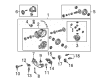
Toyota Venza Differential Carrier, Rear Part Number: 41110-58030
$1126.36 MSRP: $1650.70You Save: $524.34 (32%)Ships in 1-3 Business Days
Toyota Venza Case Part Number: 41301-21030
$535.82 MSRP: $785.26You Save: $249.44 (32%)Ships in 1-3 Business Days
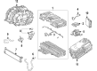
Toyota Venza Transaxle Assembly, Hev Part Number: 30970-42010
$1451.94 MSRP: $1826.32You Save: $374.38 (21%)Ships in 1-2 Business DaysToyota Venza Differential Case Part Number: 41301-48060
Toyota Venza Differential
Choose genuine Differential that pass strict quality control tests. You can trust the top quality and lasting durability. Shopping for OEM Differential for your Toyota Venza? Our website is your one-stop destination. We stock an extensive selection of genuine Toyota Venza parts. The price is affordable so you can save more. It only takes minutes to browse and find the exact fit. Easily add to cart and check out fast. Our hassle-free return policy will keep you stress-free. We process orders quickly for swift delivery. Your parts will arrive faster, so you can get back on the road sooner.
The Toyota Venza Differential plays a crucial role of a component in the car's drivetrain, enabling proper and consistent functionality in several scenarios. The differential is famous for its function of accommodating the drive wheels at unequal speeds; it upgrades the car's cornering stability and traction, which is crucial for Toyota Venza as a solid crossover SUV. Almost all Venza models have open differentials on the torque which is excellent but may prove very difficult especially on slippery terrain. However, some derivatives include limited-slip differentials (LSD), which help to provide better traction with a result that power is delivered to the wheel that has a better grip and so can enhance drivability. The differential system of Toyota Venza is versatile to allow various options such as the front wheel and the all wheel driving system for consumers. This but not only increases productivity but also greatly benefits the safety of the vehicle, this is evidenced by such test results as the IIHS awarding it the Top Safety Pick. Notably, the types of differential might be bevel or spur types and from this,Toyota was showing how much it cares about performance and reliability of the car. The maintenance of the differential should be done often so that it can continue to run effectively to enhance the performance of the Toyota Venza. Based on the features and construction of the Toyota Venza Differential the market is set to benefit from this new invention and create a unique image of the brand.
Toyota Venza Differential Parts and Q&A
- Q: How to remove and replace the differential carrier on Toyota Venza?A:The first step for differential carrier replacement requires that you verify ownership of all components needed for the rear differential carrier assembly. First disconnect the associated parts while carefully moving the carrier unit out of its housing space. Examine all components for wear before inserting the new carrier because the carrier removal process has been finished. Check alignment then fasten all connections until you finish the differential carrier installation successfully.
- Q: How to install a new rear differential carrier assembly on Toyota Venza?A:The first step for installing a new rear differential carrier assembly requires users to detach the 2 differential side seal caps while they install the rear Drive Shaft assembly. Secure the rear differential dynamic damper in position by installing a bolt which requires tightening to 27 Nm (270 kgf-cm, 20 ft-lbf). Install the rear No. 1 differential support to the rear differential carrier assembly by using new nuts and new bolts while orienting the support correctly and positioning each nut at (A). Begin attaching the differential support to the rear differential carrier assembly through torque application of 167 Nm (1700 kgf-cm, 123 ft-lbf) with the 3 new bolts. Use appropriate bolts and nuts to fasten the rear differential carrier assembly with differential support between its rear position and the front side of the rear suspension member assembly but position the nuts correctly to stop their rotational movement. The rear differential carrier assembly should be tightened with differential support through a sequence that begins with 95 Nm torque on the rear side while subsequently applying 103 Nm torque to the front side. Use two new bolts and two new nuts to connect the rear No. 1 differential support while torquing it to 86 Nm (877 kgf-cm, 63 ft-lbf) and paying attention to correct nut installation. Following the installation of the rear drive shaft snap rings and assemblies you should place the rear suspension member along with the frame wire and No. 3 floor wire (if applicable to HID headlight system) for both left and right sides. Both sides should receive rear No. 1 suspension arm assemblies installed together before the rear No. 2 suspension arm assemblies get temporarily fastened and the rear strut rod assemblies get installed. If the vehicle has HID headlight technology the installer should add the rear height control sensor sub-assembly before placing the No. 2 and No. 3 Parking Brake Cable systems. Illuminate the rear drive shaft nuts on both sides with new installation of the rear Speed Sensors. First tighten the propeller with center bearing shaft assembly temporarily before making it a full and final torque. The technician should begin by installing the No. 1 floor under cover before inspecting and adjusting the transfer oil and installing the center Exhaust Pipe assembly. The rear differential carrier assembly requires the installation of a drain plug with new gasket that must be torqued to 39 Nm (398 kgf-cm, 29 ft-lbf). Add differential oil according to measured levels. Uphold the inspection and adjustment process for differential oil followed by placement of the rear differential carrier cover plug before checking exhaust gas leak indications. The last procedure includes installing the rear wheels, torquing them to 105 Nm (1050 kgf-cm, 76 ft-lbf) before stabilizing the suspension, fully tightening all rear No. 2 suspension arm assemblies, carrying out a rear wheel alignment check, verifying the speed sensor signal, and initializing the height control sensor signal (if HID headlight system equipped) and performing headlight aiming inspection (if HID system equipped).


Related Toyota Venza Parts
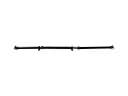 Toyota Venza Drive Shaft
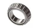 Toyota Venza Differential Bearing
 Toyota Venza Dipstick Tube
 Toyota Venza Intake Valve
 Toyota Venza Oil Drain Plug Gasket
 Toyota Venza Oil Filler Cap
 Toyota Venza Oil Pump Gasket
 Toyota Venza Pinion Bearing
 Toyota Venza Timing Chain Tensioner
 Toyota Venza Transfer Case Bearing
 Toyota Venza Transfer Case Seal
 Toyota Venza Transmission Drain Plug