×
ToyotaParts- Hello
- Login or Register
- Quick Links
- Live Chat
- Track Order
- Parts Availability
- RMA
- Help Center
- Contact Us
- Shop for
- Toyota Parts
- Scion Parts
My Garage
My Account
Cart
OEM Toyota Venza Speed Sensor
Speed Control Sensor- Select Vehicle by Model
- Select Vehicle by VIN
Select Vehicle by Model
orMake
Model
Year
Select Vehicle by VIN
For the most accurate results, select vehicle by your VIN (Vehicle Identification Number).
9 Speed Sensors found


Toyota Venza ABS Sensor, Rear Driver Side Part Number: 89546-0T011
$180.10 MSRP: $257.14You Save: $77.04 (30%)Ships in 1-3 Business Days

Toyota Venza ABS Sensor, Front Driver Side Part Number: 89543-0T011
$180.10 MSRP: $257.14You Save: $77.04 (30%)Ships in 1-3 Business Days


Toyota Venza ABS Sensor, Front Passenger Side Part Number: 89542-0T011
$180.10 MSRP: $257.14You Save: $77.04 (30%)Ships in 1-2 Business Days

Toyota Venza Vehicle Speed Sensor Part Number: 89413-08030
$202.23 MSRP: $288.74You Save: $86.51 (30%)Ships in 1 Business Day


Toyota Venza Vehicle Speed Sensor Part Number: 89413-06010
$202.23 MSRP: $288.74You Save: $86.51 (30%)Ships in 1-3 Business DaysToyota Venza ABS Sensor, Rear Passenger Side Part Number: 89545-0T011
$183.01 MSRP: $261.29You Save: $78.28 (30%)Ships in 1-3 Business Days
Toyota Venza ABS Sensor, Front Driver Side Part Number: 89543-42070
$234.85 MSRP: $335.32You Save: $100.47 (30%)Ships in 1-3 Business DaysToyota Venza ABS Sensor, Front Passenger Side Part Number: 89542-42070
$234.85 MSRP: $335.32You Save: $100.47 (30%)Ships in 1-3 Business Days
Toyota Venza Sensor, Transmission Revolution Part Number: 89413-0T010
$252.56 MSRP: $360.60You Save: $108.04 (30%)Ships in 1-3 Business Days
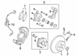
Toyota Venza Speed Sensor
Choose genuine Speed Sensor that pass strict quality control tests. You can trust the top quality and lasting durability. Shopping for OEM Speed Sensor for your Toyota Venza? Our website is your one-stop destination. We stock an extensive selection of genuine Toyota Venza parts. The price is affordable so you can save more. It only takes minutes to browse and find the exact fit. Easily add to cart and check out fast. Our hassle-free return policy will keep you stress-free. We process orders quickly for swift delivery. Your parts will arrive faster, so you can get back on the road sooner.
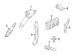
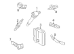
The Toyota Venza Speed Sensor is one spare part that has contributed to the improvement of the performance and safety of the Toyota Venza which is a mid-size Cross Over Vehicle (also known as CUV). This kind of Speed Sensor passes the current speed of the vehicle and the rotational speed if the wheels to the computer systems in the vehicle. With the help of VSS and WSS the Toyota Venza is able to make proper performance settings for such important systems as engine control and the anti-lock brake system. It is still one of the most safe cars, which is proved by the Insurance Institute for Highway Safety (IIHS) Top Safety Pick several times for the Toyota Venza. Passive as well as active designs of the Speed Sensor builds up very high reliability and accuracy of the speeds even in adverse environments. First of all, it is pertinent to mention that Toyota Venza Speed Sensor uses hi-technologies such as Hall effect and magnetoresistive technologies aim at optimizing and improving the output signal of the car's running efficiency. Designed for different Venza models, this Speed Sensor helps to uphold the driving characteristics and safety features of the car. It can also help in providing real time information not only in efficient driving but also safe driving. Being one of the most trustworthy and result-oriented Scion components, Toyota Venza Speed Sensor is a prominent vehicle in the automotive industry, and with good reason - for any Toyota Venza owner, it is a crucial part of maintaining the car's reliability and safety.
Toyota Venza Speed Sensor Parts and Q&A
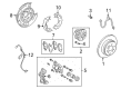
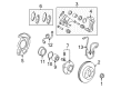
- Q: How to install the front speed sensor on Toyota Venza?A:Start by repeating the front speed sensor installation process for both left-hand (LH) and right-hand (RH) sides and then follow the next steps regarding the LH side. The front sensor rotor needs to replace at the same time when repairing the front Drive Shaft assembly. Fitting the resin clamp along with the front speed sensor requires applying an 8.0 Nm (82 kgf-cm, 71 in-lbf) torque on the bolt. Tightening the bolt needs to be done after the front speed sensor is properly inserted into the knuckle with no foreign matter attached to its tip. Furthermore, check for clearance and debris between the front speed sensor stay and knuckle. Begin by installing the No. 1 sensor clamp but only for brief installation which should penetrate the stopper hole with the claw. Install the front brake flexible hose together with the No. 1 sensor clamp to the Shock Absorber and use a bolt that requires 19 Nm (194 kgf-cm, 14 ft-lbf) torque while maintaining the front speed sensor wire harness straight and positioning the flexible hose over the sensor. Position the No. 2 sensor clamp to the body with a bolt and apply torque at 5.0 Nm (51 kgf-cm, 44 in-lbf). Then, install both clamps and connect the front speed sensor connector. Mount both the front fender liner LH and the front fender outside moulding LH. The installation process continues with attaching the front wheel using 103 Nm torque while following up with reconnecting the negative cable to the battery terminal and observing system requirements for post-reconnection procedures. The speed sensor signal needs to be tested as the final step.
- Q: How to remove the rear speed sensor on Toyota Venza?A:The rear speed sensor removal for AWD starts with disconnecting the cable from the negative battery terminal while initialization after reconnection might be necessary for some systems. The removal process begins by taking off the rear wheel then continuing with the rear door scuff plate LH and rear door opening trim Weather Strip LH, tonneau cover assembly and deck board assembly and moving to No. 3 deck board sub-assembly before proceeding with deck side trim box LH and No. 2 deck board sub-assembly and deck side trim box RH and finishing with the removal of No. 1 deck board. The technician must remove the rear seat sub floor panel assembly together with the rear floor finish plate and reclining remote control bezel LH and luggage hold belt striker assembly. To get access, first detach the rear seat outer belt assembly LH followed by a removal of deck trim side panel assembly LH. The removal process of the rear speed sensor includes disconnecting its connector followed by removing the grommet from the rear speed sensor wire in the wheel house, then unscrewing the body's 2 bolts and No. 1 and No. 2 clamps before detaching the sensor bolt from the carrier while ensuring complete clearance of foreign matter from both the installation hole and sensor tip.


Related Toyota Venza Parts
 Toyota Venza ABS Pump And Motor Assembly
 Toyota Venza Backing Plate
 Toyota Venza Brake Caliper
 Toyota Venza Brake Caliper Piston
 Toyota Venza Brake Drum
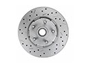 Toyota Venza Brake Rotor
 Toyota Venza Hydraulic Hose
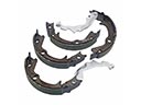 Toyota Venza Parking Brake Shoes
 Toyota Venza Spindle Nut
 Toyota Venza Wheel Cylinder
 Toyota Venza Wheel Hub
 Toyota Venza Yaw Sensor