×
ToyotaParts- Hello
- Login or Register
- Quick Links
- Live Chat
- Track Order
- Parts Availability
- RMA
- Help Center
- Contact Us
- Shop for
- Toyota Parts
- Scion Parts
My Garage
My Account
Cart
OEM Toyota Venza Yaw Sensor
Yaw Rate Sensor- Select Vehicle by Model
- Select Vehicle by VIN
Select Vehicle by Model
orMake
Model
Year
Select Vehicle by VIN
For the most accurate results, select vehicle by your VIN (Vehicle Identification Number).
1 Yaw Sensor found


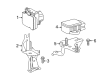
Toyota Venza Yaw Rate Sensor Part Number: 89183-0T010
$306.97 MSRP: $438.28You Save: $131.31 (30%)Ships in 1-3 Business Days
Toyota Venza Yaw Sensor
Choose genuine Yaw Sensor that pass strict quality control tests. You can trust the top quality and lasting durability. Shopping for OEM Yaw Sensor for your Toyota Venza? Our website is your one-stop destination. We stock an extensive selection of genuine Toyota Venza parts. The price is affordable so you can save more. It only takes minutes to browse and find the exact fit. Easily add to cart and check out fast. Our hassle-free return policy will keep you stress-free. We process orders quickly for swift delivery. Your parts will arrive faster, so you can get back on the road sooner.
The Yaw Sensor for Toyota Venza exists as an essential technological element which brings better reliability and performance to Toyota's Venza mid-size crossover SUV model. The sensor tracks precise movements of vertical axis rotations called yaw to deliver critical data that enhances stability control functions under emergency driving and improper surface conditions. The safety systems of a Toyota Venza depend on the Yaw Sensor to maintain handling stability and performance by automatically adjusting to altered vehicle height when passengers or cargo enter or exit the vehicle. All these adaptive functions defend the undercarriage components of the vehicle while improving overall driving effectiveness. The Toyota Venza series which started production in 2008 has established its prominence because the Insurance Institute for Highway Safety (IIHS) honored it with its Top Safety Pick designation multiple times. The Yaw Sensor operates well with all versions of the Toyota Venza starting from its original release in 2008 through its current iterations which proves its importance for vehicle performance maintenance. The special features of Toyota Venza Yaw Sensor include real-time data processing which develops both safer driving conditions and delivers better vehicle performance. The Yaw Sensor for the brand model establishes itself as an automotive market standout due to its demonstration of the automaker's dedication to creating advanced safety technologies and top performance standards.
Toyota Venza Yaw Sensor Parts and Q&A
- Q: How to install a Yaw Sensor and its associated components on Toyota Venza?A:A torque of 5.0 Nm (51 kgf-cm, 44 in-lbf) should be applied to the 2 nuts that secure the yaw rate and acceleration sensor to the bracket while 2 bolts need 13 Nm (127 kgf-cm, 9 ft-lbf) torque for sensor-bracket attachment. This process must include placement of the sensor claw into the stopper hole and must prevent damage or looseness. Connect the sensor connector until it is firmly secured. You must install the No. 4 center member floor reinforce sub-assembly using 7 bolts with 19 Nm (194 kgf-cm, 14 ft-lbf) torque before you remove the floor carpet to its previous arrangement. Proceed to install the console box sub-assembly, position indicator housing assembly, shift lever knob sub-assembly, lower instrument panel sub-assembly, No. 2 instrument panel under cover sub-assembly, cowl side trim sub-assembly RH, front door scuff plate RH, lower No. 1 instrument panel finish panel, cowl side trim sub-assembly LH, front door scuff plate LH, air conditioning control assembly, console box assembly, No. 2 console box carpet, upper console panel sub-assembly (with or without seat heater system), and the front seat assemblies LH and RH (for both manual and power seats). After cable connection to the negative battery terminal some systems may need initialization procedures along with SRS warning light inspection.

Related Toyota Venza Parts
 Toyota Venza Brake Pads
 Toyota Venza Speed Sensor
 Toyota Venza Wheel Bearing
 Toyota Venza ABS Pump And Motor Assembly
 Toyota Venza Backing Plate
 Toyota Venza Brake Caliper Bracket
 Toyota Venza Brake Drum
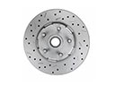 Toyota Venza Brake Rotor
 Toyota Venza Brake Shoe Set
 Toyota Venza Hydraulic Hose
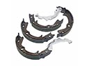 Toyota Venza Parking Brake Shoes
 Toyota Venza Wheel Hub